Toyota Sienna Service Manual: Power back door drive unit
INSPECTION
1. INSPECT POWER BACK DOOR DRIVE UNIT
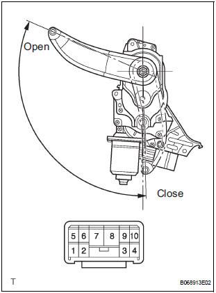
- Remove the unit.
- Apply battery voltage to the terminals and check the motor operation.
Standard
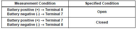
If the result is not as specified, replace the drive unit.
- Check the resistance of the clutch terminals.
Resistance
If the result is not as specified, replace the drive unit.
- Reinstall the unit with the connector connected.
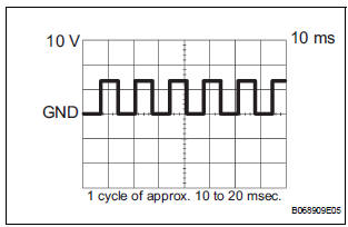
- Check the pulse of the pulse sensor.
- Using an oscilloscope, check the pulse generated when the door is manually opened and closed.
Standard (Reference)
If the result is not as specified, replace the drive unit.
HINT: A cycle of the pulse changes between approx.
10 to 20 msec. according to the speeds that the slide door is moving.
- With the connector connected, check the voltage of the terminals of the power back door drive unit connector.
 Power back door touch sensor
INSPECTION
1. INSPECT POWER BACK DOOR TOUCH SENSOR LH
Check the resistance of the sensor.
Resistance
If the result is not as specified, replace the sensor.
2. INSPECT POWER BACK DOOR T ...
 Power back door warning buzzer
INSPECTION
1. POWER BACK DOOR WARNING BUZZER
Check the resistance of the buzzer.
Resistance
If the result is not as specified, replace the buzzer.
NOTICE:
The circuit that causes t ...
Other materials:
Towing with a wheel-lift type truck
From the front (2WD models)
Release the parking brake.
From the front (AWD models)
Use a towing dolly under the rear
wheels.
From the rear
Use a towing dolly under the front
wheels. ...
How to proceed with
troubleshooting
HINT:
Use this procedure to troubleshoot the theft deterrent
system.
The intelligent tester should be used in step 2.
1 VEHICLE BROUGHT TO WORKSHOP
2 CUSTOMER PROBLEM ANALYSIS
Interview the customer to confirm the trouble
3 INSPECT COMMUNICATION FUNCTION OF MULTIPLEX COMMUNI ...
Removal
1. RECOVER REFRIGERANT FROM REFRIGERATION
SYSTEM (See page AC-172)
2. REMOVE FRONT WHEEL RH
3. REMOVE FRONT FENDER APRON SEAL RH (See
page EM-26)
4. REMOVE V-RIBBED BELT (See page EM-6)
5. REMOVE RADIATOR AND FAN ASSEMBLY
(See page CO-28)
6. DISCONNECT DISCHARGE HOSE SUB-ASSEMBLY
(a) Re ...
