Toyota Sienna 2010-2026 Owners Manual: Using the rear view monitor system
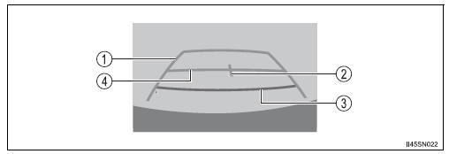
Screen description
The rear view monitor system screen will be displayed if the shift lever is shifted to R while the engine switch is in the “ON” position (vehicles without a smart key system) or IGNITION ON mode (vehicles with a smart key system).

- Vehicle width guide line
The line indicates a guide path when the vehicle is being backed straight
up.
The displayed width is wider than the actual vehicle width.
- Vehicle center guide line These lines indicate the estimated vehicle center on the ground.
- Distance guide line
The line shows distance behind the vehicle, a point approximately 1.5 ft.
(0.5 m) (red) from the edge of the bumper.
- Distance guide line
The line shows distance behind the vehicle, a point approximately 3 ft.
(1 m) (blue) from the edge of the bumper.
 Rear view monitor
system
The rear view monitor system assists the driver by displaying an
image of the view behind the vehicle and guide lines while backing
up, for example while parking.
The screen illustrations used in t ...
 Rear view monitor system precautions
Area displayed on screen
The rear view monitor system
displays an image of the view
from the bumper of the rear
area of the vehicle.
The image on the rear view monitor system can be adjusted.
...
Other materials:
Security Horn Circuit
DESCRIPTION
During the alarm sounding state, the relay in the ECU turns on and off in a
cycle of approximately 0.2
seconds, causing the security horn to sound.
WIRING DIAGRAM
INSPECTION PROCEDURE
1 INSPECT SECURITY HORN ASSEMBLY
Disconnect the T1 security horn connector.
C ...
AVC-LAN Circuit
DESCRIPTION
Each unit of the navigation system connected to the AVC-LAN (communication
bus) transfers the signal of
each switch by communication.
When a short to +B or short to ground occurs in this AVC-LAN, the navigation
system will not function
normally as the communication is discontin ...
Front seat frame with adjuster
Inspection
1. INSPECT FRONT SEAT ADJUSTER SUB-ASSEMBLY LH
Check operation of the seat frame (slide motor).
Check if the seat frame moves smoothly when
the battery is connected to the slide motor
connector terminals.
OK
If the result is not as specified, replace t ...
