Toyota Sienna Service Manual: Compressor Solenoid Circuit
DESCRIPTION
In this circuit, the compressor receives a refrigerant compression demand signal from the A/C amplifier.
Based on this signal, the compressor changes the amount of compressor output.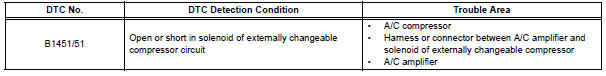
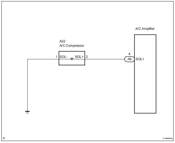
WIRING DIAGRAM
INSPECTION PROCEDURE
1 INSPECT A/C COMPRESSOR
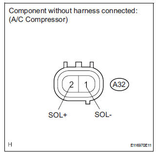
(a) Disconnect the A/C compressor connector.
(b) Measure the resistance according to the value(s) in the table below.
Standard resistance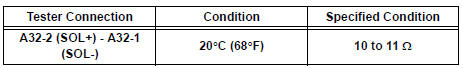


2 CHECK HARNESS AND CONNECTOR (A/C COMPRESSOR - BODY GROUND)
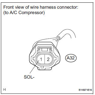
(a) Disconnect the A/C compressor connector.
(b) Measure the resistance according to the value(s) in the table below.
Standard resistance 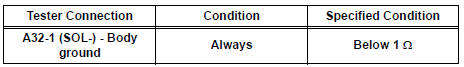

3 CHECK HARNESS AND CONNECTOR (A/C COMPRESSOR - A/C AMPLIFIER)
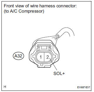
(a) Disconnect the A/C compressor connector.
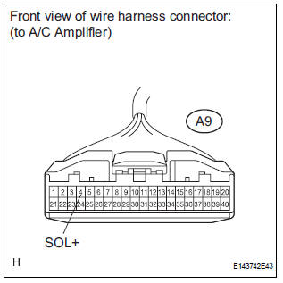
(b) Disconnect the A/C amplifier connector.
(c) Measure the resistance according to the value(s) in the table below
Standard resistance 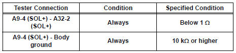
Result 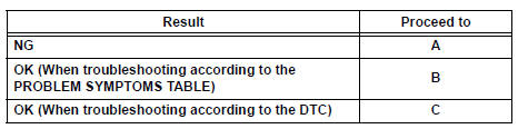

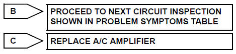
REPAIR OR REPLACE HARNESS OR CONNECTOR
 Rear Air Outlet Damper Control Servo Motor Circuit
DESCRIPTION
This circuit turns the servo motor and changes each damper position by
receiving the signals from the A/
C amplifier.
The rear air outlet damper servo motor switches the air outlet ...
 Multiplex Communication Circuit
DESCRIPTION
INSPECTION PROCEDURE
1 GO TO CAN COMMUNICATION SYSTEM
(a) Refer to the CAN communication system (See page CA-
7).
(b) If the CAN communication system is operating normally,
procee ...
Other materials:
Camshaft Position "A" Actuator Circuit
DTC P0010 Camshaft Position "A" Actuator Circuit (Bank
1)
DTC P0020 Camshaft Position "A" Actuator Circuit (Bank
2)
DESCRIPTION
The Variable Valve Timing (VVT) system includes the ECM, Oil Control Valve (OCV)
and VVT controller.
The ECM sends a target duty-cycle control ...
Disassembly
1. REMOVE BRAKE MASTER LESS RESERVOIR TANK CYLINDER SUB-ASSEMBLY
(a) Using soft jaws on the vise, hold the brake master
cylinder in a vise through aluminum plates.
(b) Using a screwdriver, remove the O-ring.
(c) Using SST, remove the brake tube from the brake
master cylinder.
SST 09023 ...
Skid Control ECU Communication Stop Mode
DESCRIPTION
Detection Item
Symptom
Trouble Area
Skid Control ECU
Communication Stop
Mode
"ABS/VSC/TRC" is not displayed on the
"Communication Bus Check" screen of the
intelligent tester
Applies to "Skid Control ...
