Toyota Sienna Service Manual: Installation
1. TEMPORARILY TIGHTEN AIR CONDITIONING UNIT ASSEMBLY
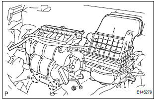
(a) Engage the 2 claws.
(b) Temporarily tighten the air conditioning unit assembly with the nut.
Torque: 9.8 N*m (100 kgf*cm, 87 in.*lbf)
2. INSTALL LOWER DEFROSTER NOZZLE ASSEMBLY
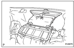
(a) Engage the 4 claws and install the lower defroster nozzle assembly.
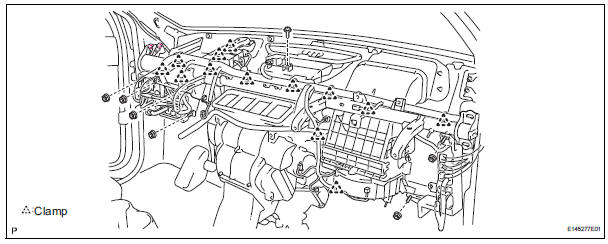
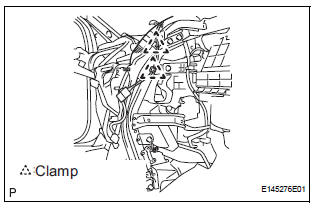
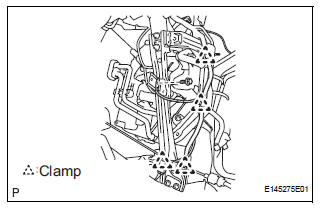
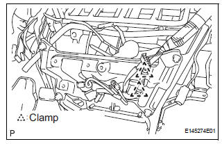
3. INSTALL INSTRUMENT PANEL REINFORCEMENT
(a) Install the instrument panel reinforcement with the 10 bolts.
(b) Install the 13 clamps.
(c) Connect the connectors.
(d) Install the screw.
(e) Install the 6 nuts.
Torque: 7.3 N*m (74 kgf*cm, 65 in.*lbf)
4. INSTALL AIR CONDITIONING UNIT ASSEMBLY
(a) Install the air conditioner unit assembly with the 3 bolts and 2 nuts.
Torque: 9.8 N*m (100 kgf*cm, 87 in.*lbf)
5. INSTALL FRONT FENDER GARNISH RH
6. INSTALL ECM (See page ES-499)
7. INSTALL STEREO COMPONENT AMPLIFIER ASSEMBLY (w/ Stereo Component Amplifier) (See page AV-173)
8. INSTALL NO. 2 INSTRUMENT PANEL BRACE SUBASSEMBLY
(a) Install the No. 2 instrument panel brace subassembly with the 3 bolts and 2 nuts.
(b) Engage the 2 clamps.
(c) Connect the connector.
9. INSTALL NO. 1 INSTRUMENT PANEL BRACE SUBASSEMBLY
(a) Install the No. 1 instrument panel brace subassembly with the 3 bolts and 2 nuts.
(b) Engage the 4 clamps.
(c) Install the bolt.
(d) Connect the connector.
10. INSTALL NO. 5 INSTRUMENT PANEL BRACKET
(a) Install the No. 5 instrument panel bracket with the 4 nuts.
(b) Engage the 2 clamps.
(c) Connect the connector.
11. INSTALL SHIFT LEVER ASSEMBLY
HINT: (See page AX-150 for U151E, AX-150 for U151F)
12. CONNECT TRANSMISSION CONTROL CABLE ASSEMBLY
HINT: (See page AX-156 for U151E, AX-156 for U151F)
13. INSTALL STEERING COLUMN ASSEMBLY (See page SR-10)
14. CONNECT STEERING INTERMEDIATE SHAFT ASSEMBLY (See page SR-10)
15. INSTALL NO. 1 HEATER TO FOOT DUCT
(a) Install the No. 1 heater to foot duct with the clip.
16. INSTALL NO. 3 HEATER TO FOOT DUCT
(a) Install the No. 3 heater to foot duct with the clip.
17. INSTALL SPIRAL CABLE (See page RS-434)
18. INSTALL INSTRUMENT PANEL ASSEMBLY WITH PASSENGER AIRBAG ASSEMBLY
HINT: (See page IP-14)
19. INSTALL HEATER WATER INLET HOSE A
20. CONNECT HEATER WATER OUTLET HOSE A (FROM HEATER UNIT)
(a) Using pliers, grip the claws of the clip and slide the clip to connect the heater water outlet hose A (from heater unit).
21. INSTALL AIR CLEANER CAP SUB-ASSEMBLY (See page IT-5)
22. INSTALL SUCTION HOSE SUB-ASSEMBLY
(a) Lubricate a new O-ring with compressor oil and install it on the hose.
Compressor oil: ND-OIL 8 or equivalent
(b) Install the suction hose sub-assembly and the piping clamp.
HINT: After the connection, check the claw fitting of the piping clamp.
23. INSTALL COOLER REFRIGERANT LIQUID PIPE E (TO COOLER UNIT)
(a) Lubricate a new O-ring with compressor oil and install it to the pipe.
Compressor oil: ND-OIL 8 or equivalent
(b) Install the cooler refrigerant liquid pipe E and the piping clamp.
HINT: After the connection, check the claw fitting of the piping clamp.
24. INSTALL FRONT COWL TOP OUTER PANEL SUBASSEMBLY (See page SP-18)
25. INSTALL WINDSHIELD WIPER MOTOR AND LINK ASSEMBLY (See page WW-6)
26. INSTALL COWL TOP VENTILATOR LOUVER SUBASSEMBLY (See page WW-6)
27. INSTALL FRONT WIPER ARM LH (See page WW-6)
28. INSTALL FRONT WIPER ARM RH (See page WW-7)
29. INSTALL FRONT WIPER ARM HEAD CAP (See page WW-7)
30. ADJUST SHIFT LEVER POSITION
HINT: (See page AX-149 for U151E, AX-149 for U151F)
31. INSPECT SHIFT LEVER POSITION
HINT: (See page AX-152 for U151E, AX-152 for U151F)
32. INSPECT KEY INTERLOCK OPERATION
HINT: (See page AX-152 for U151E, AX-152 for U151F)
33. INSPECT SHIFT LOCK OPERATION
HINT: (See page AX-152 for U151E, AX-152 for U151F)
34. INSPECT SHIFT LOCK RELEASE BUTTON OPERATION
HINT: (See page AX-152 for U151E, AX-152 for U151F)
35. ADD ENGINE COOLANT (See page CO-7)
36. CHARGE WITH REFRIGERANT (See page AC-173)
37. WARM UP ENGINE
38. INSPECT FOR ENGINE COOLANT LEAK (See page CO-1)
39. INSPECT FOR REFRIGERANT LEAK (See page AC- 173)
 Reassembly
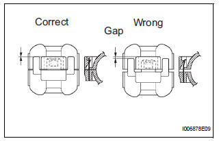
1. INSTALL NO. 1 COOLER THERMISTOR
(a) Install the No. 1 cooler thermistor as shown in the
illustration.
NOTICE:
Be sure to insert the thermistor only once
because reinserting it will no ...
 Blower unit
COMPONENTS
...
Other materials:
Installation
HINT:
Use the same procedures for the RH side and LH side.
The procedures listed below are for the LH side.
1. INSTALL REAR AIRBAG SENSOR LH
Check that the ignition switch is off.
Check that the battery negative (-) terminal is
disconnected.
CAUTION:
...
Front Occupant Classification Sensor RH Circuit
Malfunction
DTC B1781 Front Occupant Classification Sensor RH Circuit
Malfunction
DESCRIPTION
The front occupant classification sensor RH circuit consists of the occupant
classification ECU and the
front occupant classification sensor RH.
DTC B1781 is recorded when a malfunction is detected in the fron ...
Skid Control ECU Communication Stop Mode
DESCRIPTION
Detection Item
Symptom
Trouble Area
Skid Control ECU
Communication Stop
Mode
"ABS/VSC/TRC" is not displayed on the
"Communication Bus Check" screen of the
intelligent tester
Applies to "Skid Control ...
