Toyota Sienna Service Manual: Installation
1. INSTALL COMPRESSOR AND MAGNETIC CLUTCH
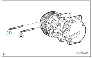
(a) Using a "TORX" socket wrench (E8), install the compressor and magnetic clutch with the 2 stud bolts.
Torque: 10 N*m (102 kgf*cm, 7.4 ft.*lbf)
HINT: Tighten the stud bolts in the order shown in the illustration.
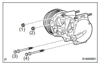
(b) Install the compressor and magnetic clutch with the 2 bolts and the 2 nuts.
Torque: 25 N*m (255 kgf*cm, 18 ft.*lbf)
HINT: Tighten the bolts and nuts in the order shown in the illustration.
(c) Connect the 2 clamps and wire harness.
(d) Connect the connector.
2. INSTALL SUCTION HOSE SUB-ASSEMBLY
(a) Remove the attached vinyl tape from the hose.
(b) Apply sufficient compressor oil to a new O-ring and the fitting surface of the compressor and magnetic clutch.
Compressor oil: ND-OIL 8 or equivalent
(c) Install the O-ring onto the suction hose subassembly.
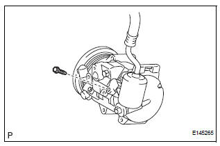
(d) Install the suction hose sub-assembly onto the compressor and magnetic clutch with the bolt.
Torque: 5.4 N*m (55 kgf*cm, 48 in.*lbf)
3. INSTALL DISCHARGE HOSE SUB-ASSEMBLY
(a) Remove the attached vinyl tape from the hose.
(b) Apply sufficient compressor oil to a new O-ring and the fitting surface of the compressor and magnetic clutch.
Compressor oil: ND-OIL 8 or equivalent
(c) Install the O-ring onto the discharge hose subassembly.
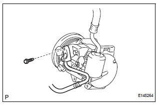
(d) Install the discharge hose sub-assembly onto the compressor and magnetic clutch with the bolt.
Torque: 5.4 N*m (55 kgf*cm, 48 in.*lbf)
4. INSTALL RADIATOR AND FAN ASSEMBLY
(See page CO-39)
5. INSTALL V-RIBBED BELT (See page EM-7)
6. INSTALL FRONT FENDER APRON SEAL RH (See page EM-62)
7. INSTALL FRONT WHEEL RH
8. CHARGE WITH REFRIGERANT (See page AC-173)
9. WARM UP ENGINE
10. INSPECT FOR REFRIGERANT LEAK (See page AC- 173)
 Reassembly
1. INSTALL MAGNETIC CLUTCH ASSEMBLY
(a) Install the magnetic clutch stator while aligning the
protrusion on the stator with the notch on the air
compressor assembly as shown in the illustration ...
 Condenser
COMPONENTS
...
Other materials:
CD-ROM Abnormal/ CD-ROM Abnormal
DTC 62-43 CD-ROM Abnormal
DTC 63-43 CD-ROM Abnormal
DESCRIPTION
DTC No.
DTC Detecting Condition
Trouble Area
62-43
CD-ROM operation is abnormal
CD
Radio receiver
63-43
CD-ROM operation is abnormal
INSPECTION PROCEDURE
HIN ...
Removal
1. REMOVE INSTRUMENT PANEL SAFETY PAD SUBASSEMBLY
2. REMOVE ANTENNA CORD SUB-ASSEMBLY
Replace the 5 clamps and remove the antenna cord
sub-assembly.
3. REMOVE PULL TOP ANTENNA POLE SUBASSEMBLY
4. REMOVE ANTENNA ORNAMENT
Remove the antenna ornament.
5. REMOVE ANTENNA ASS ...
Sound Signal Circuit between Radio Receiver and Stereo Component
Amplifier
DESCRIPTION
The radio receiver sends a sound signal to the stereo component amplifier
through this circuit.
The sound signal that has been sent is amplified by the stereo component
amplifier, and then is sent to
the speakers.
If there is an open or short in the circuit, sound cannot be h ...
