Toyota Sienna Service Manual: Active Control Engine Mount System
DESCRIPTION
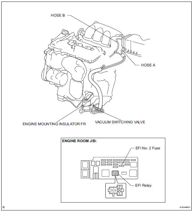
LOCATION
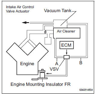
The Active Control Engine Mount (ACM) system decreases engine vibration at engine idling using the ACM VSV. The VSV is controlled by a pulse signal transmitted to the VSV from the ECM. The frequency of this pulse signal is matched to the engine speed to decrease engine vibration.
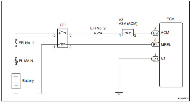
WIRING DIAGRAM
INSPECTION PROCEDURE
1 CHECK VACUUM HOSES
- If the hose is damaged, replace the vacuum hose assembly.
- Check the air and vacuum hoses for looseness, disconnection and blockage.
2 CHECK VACUUM
- Start the engine.
- Disconnect the vacuum hose from the air cleaner cap.
- Check that the disconnected port located on the vacuum
tank applies suction to your finger.
OK: Vacuum pressure exists.
- Reconnect the vacuum hose.
3 INSPECT ECM
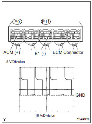
- Connect the oscilloscope between terminals ACM and E1 of the E9 and E11 ECM connectors.
- Warm up the engine to normal operating temperature.
- Turn the A/C switch on.
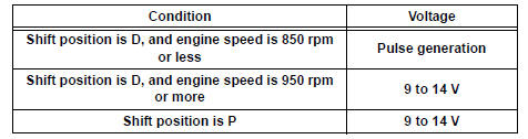
- Measure the voltage according to the value(s) in the table below.
Standard voltage
4 INSPECT DUTY VACUUM SWITCHING VALVE (RESISTANCE)
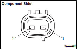
- Disconnect the V3 VSV for ACM connector.
- Measure the resistance according to the value(s) in the
table below.
Standard resistance: 19 to 21 Ω at 20C (68F)
- Reconnect the VSV for ACM connector.
5 CHECK HARNESS AND CONNECTOR (VSV FOR ACM - ECM)
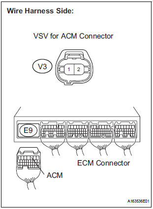
- Check the wire harness between the VSV for ACM connector and the ECM connector.
- Disconnect the V3 VSV for ACM connector.
- Disconnect the E9 ECM connector.
- Measure the resistance according to the value(s) in the table below.
Standard resistance: Check for open
Check for open
- Reconnect the ECM connector.
6 INSPECT FUSE (EFI NO. 2 FUSE)
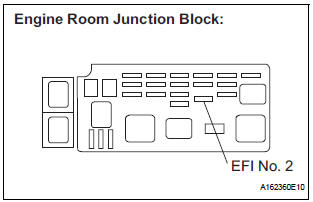
- Remove the EFI No. 2 fuse from the engine room junction block.
- Measure the resistance according to the value(s) in the
table below.
Standard resistance: Below 1 Ω
- Reinstall the EFI No. 2 fuse.
7 INSPECT RELAY (EFI RELAY)
- Remove the EFI relay from the engine room junction block.
- Measure the resistance according to the value(s) in the table below.
Standard resistance
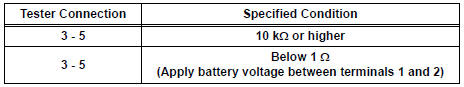
- Reinstall the EFI relay.
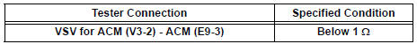
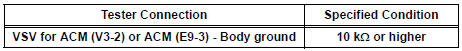
8 CHECK HARNESS AND CONNECTOR (VSV FOR ACM - EFI RELAY)
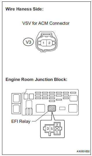
- Check the wire harness between the VSV for ACM and the EFI relay.
- Remove the EFI relay from the engine room junction block.
- Measure the resistance according to the value(s) in the table below.
Standard resistance: Check for open
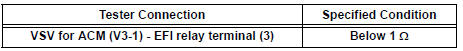
- Reconnect the VSV for ACM connector.
- Reinstall the EFI relay.
CHECK ECM POWER SOURCE CIRCUIT
9 INSPECT DUTY VACUUM SWITCHING VALVE (OPERATION)
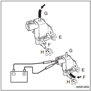
- Remove the VSV for ACM.
- Check operation of the VSV for ACM when positive
battery voltage is applied to the terminals of the VSV for
ACM connector.
Positive battery voltage is not applied: The air from pipe G is flowing out through pipes E and H.
Positive battery voltage is applied: The air from pipe F is flowing out through pipes E and H.
- Reinstall the VSV for ACM.
10 INSPECT ENGINE MOUNTING INSULATOR ASSEMBLY FRONT
- Disconnect the vacuum hose from the front engine mount insulator.
- Using a vacuum pump, apply vacuum of 80 kPa (600 mmHg, 25 in.Hg) and wait for 1 minute.
- Check that there is no change in the needle movement of the vacuum pump gauge.
- Check that there is no fluid leakage caused by a break in
the diaphragm.
OK: Vacuum pressure exists.
- Reconnect the vacuum hose.
SYSTEM OK
 A/F Sensor Circuit Slow Response
DTC P2A00 A/F Sensor Circuit Slow Response (Bank 1
Sensor 1)
DTC P2A03 A/F Sensor Circuit Slow Response (Bank 2
Sensor 1)
HINT:
DTC P2A00 indicates malfunctions related to the bank 1 A/F ...
 EVAP System
RELATED DTCS
If any EVAP system DTCs are set, the malfunctioning area can be determined
using the table below.
NOTICE:
If the 0.02 inch reference pressure difference between the first and ...
Other materials:
Terminals of ECU
1. POSITION CONTROL ECU AND SWITCH ASSEMBLY
(POWER SEAT CONTROL SWITCH AND ECU)
Disconnect the P58 and P59 connectors.
Check the voltage of each terminal of the wire
harness side connectors.
If the result is not as specified, there may be a
malfunction in the wire harn ...
Installation
1. INSTALL ROOF HEADLINING ASSEMBLY
w/ sliding roof:
Install the roof headlining with the 5 clips.
w/o sliding roof:
Install the roof headlining with the 3 clips.
NOTICE:
In order to prevent the roof headlining from
becoming bent, work must be performed by 2 or
more persons when ...
Memory recall function
Each electronic key can be registered to recall your preferred driving
position.
Registering procedure
Record your driving position to button “1” or “2” before performing
the following:
Carry only the key you want to register, and then close the driver’s
door.
If 2 or more keys ar ...
