Toyota Sienna Service Manual: Diagnostic trouble code chart
HINT: The parameters listed in the chart may not confirm exactly to those read during the DTC check due to the type of instrument or other factors.
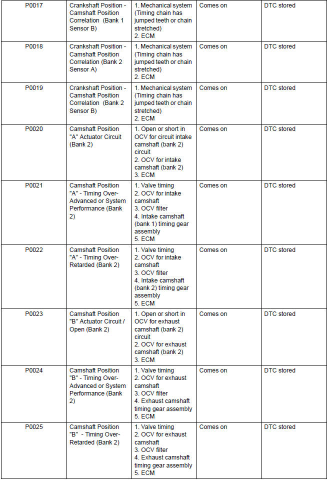
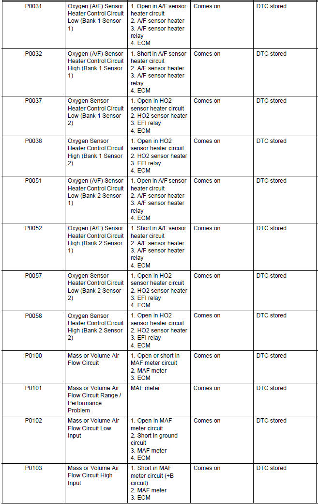
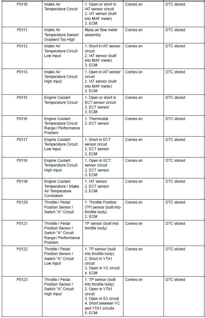
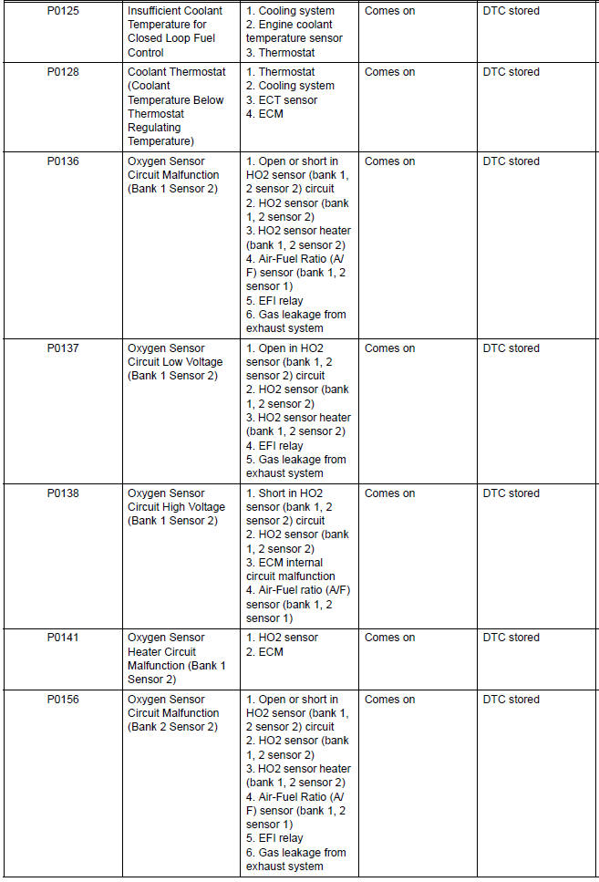
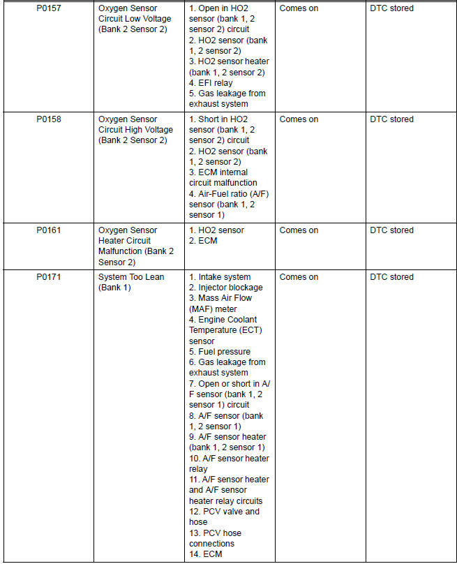
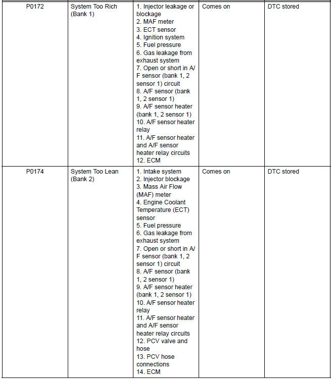
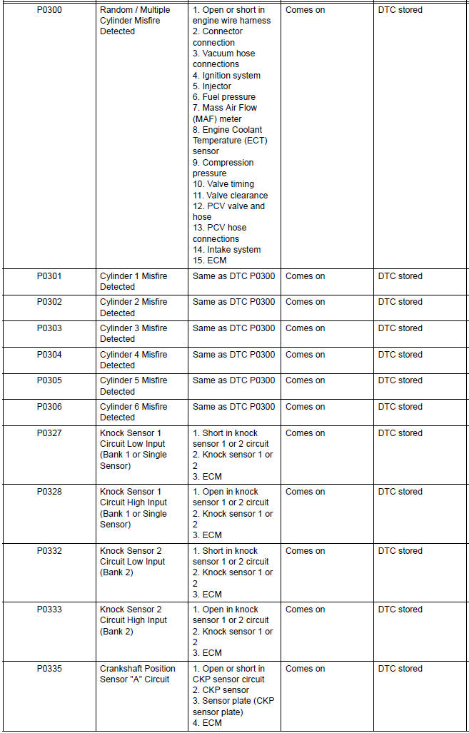
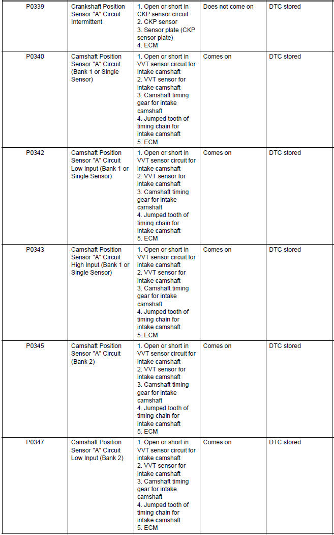
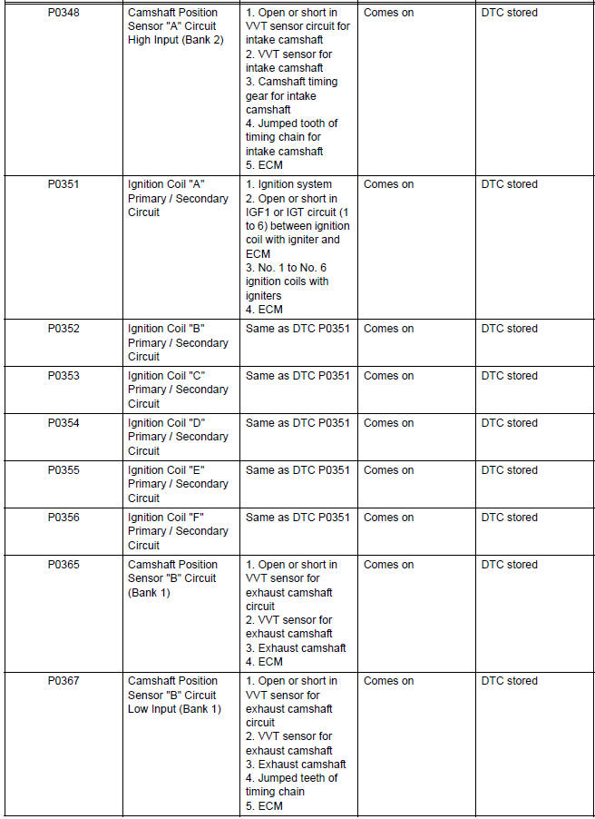
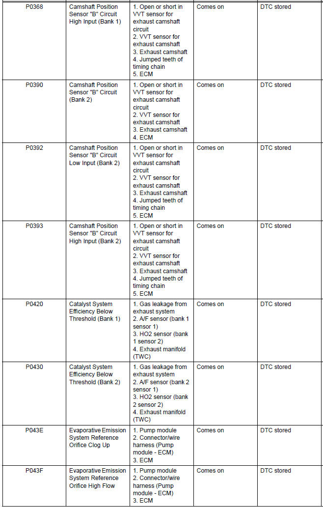
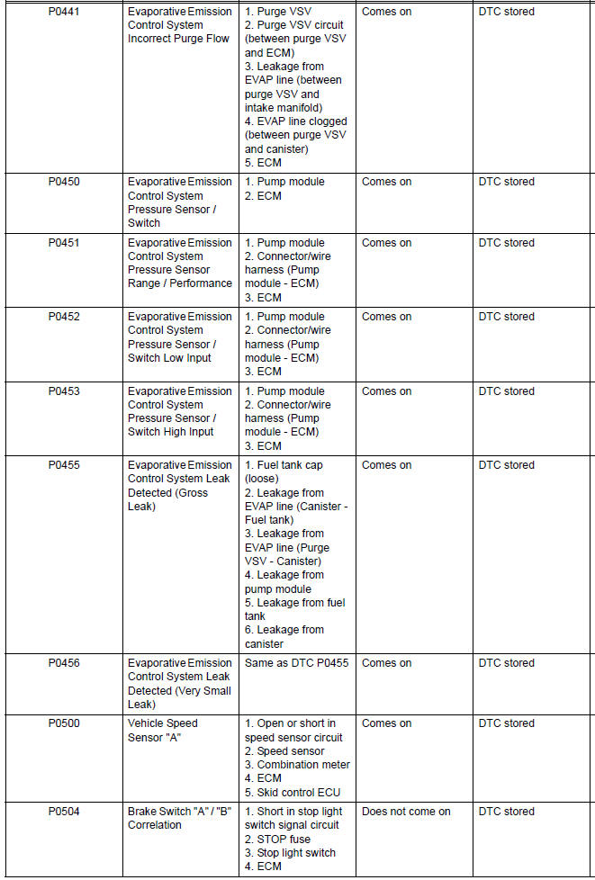
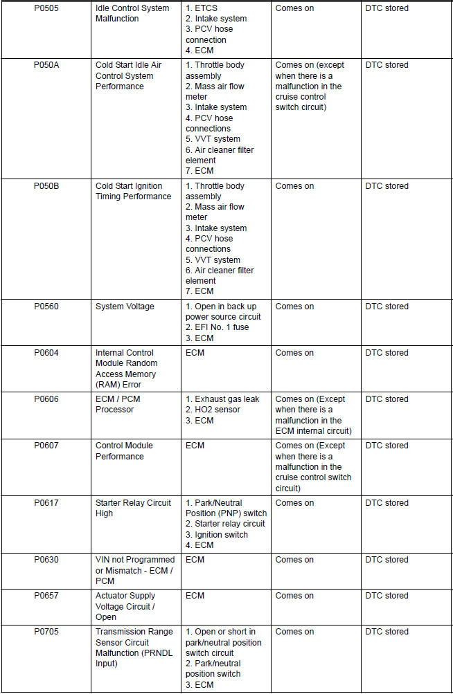
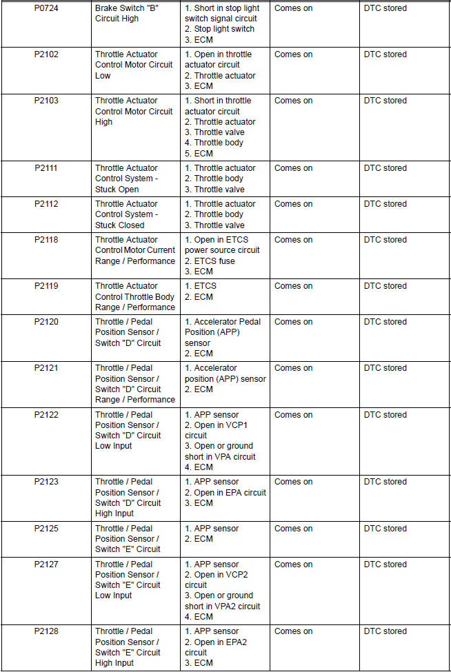
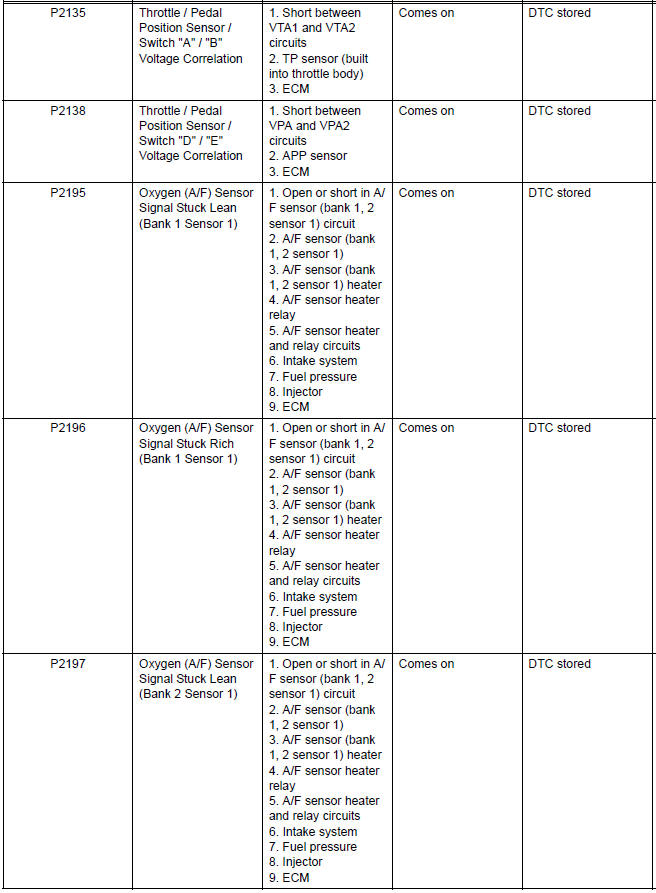
If a trouble code is displayed during the DTC check in the check mode, check the circuit for the code listed in the table below. For details of each code, refer to the "See page" column in the DTC chart.
SFI SYSTEM:
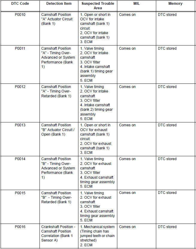
- Camshaft Position "A" Actuator Circuit
- Camshaft Position "A" - Timing Over-Advanced
- Camshaft Position "B" Actuator Circuit / Open
- Camshaft Position "B" - Timing Over-Advanced
- Crankshaft Position - Camshaft Position Correlation
- Oxygen (A/F) Sensor Heater Control Circuit Low/ Oxygen (A/F) Sensor Heater Control Circuit High
- Oxygen Sensor Heater Control Circuit Low/ Oxygen Sensor Heater Control Circuit High/ Oxygen Sensor Heater Circuit Malfunction
- Mass or Volume Air Flow Circuit/ Mass or Volume Air Flow Circuit Low Input/ Mass or Volume Air Flow Circuit High Input
- Mass or Volume Air Flow Circuit Range / Performance Problem
- Intake Air Temperature Circuit/ Intake Air Temperature Circuit Low Input/ Intake Air Temperature Circuit High Input
- Intake Air Temperature Sensor Gradient Too High
- Engine Coolant Temperature Circuit
- Engine Coolant Temperature Circuit Range / Performance Problem
- Engine Coolant Temperature / Intake Air Temperature Correlation
- Throttle / Pedal Position Sensor / Switch "A/B" Circuit
- Throttle / Pedal Position Sensor / Switch "A" Circuit Range / Performance Problem
- Insufficient Coolant Temperature for Closed Loop Fuel Control
- Coolant Thermostat (Coolant Temperature Below Thermostat Regulating Temperature)
- Oxygen Sensor Circuit Malfunction/ Oxygen Sensor Circuit Low Voltage/ Oxygen Sensor Circuit High Voltage
- System Too Lean/ System Too Rich
- Fuel Pump Primary Circuit
- Random / Multiple Cylinder Misfire Detected/ Cylinder Misfire Detected
- Knock Sensor Circuit Low Input/ Knock Sensor Circuit High Input
- Crankshaft Position Sensor "A" Circuit
- Camshaft Position Sensor "A" Circuit
- Ignition Coil Primary / Secondary Circuit
- Camshaft Position Sensor
- Catalyst System Efficiency Below Threshold
- Evaporative Emission System
- Evaporative Emission Control System Incorrect Purge Flow
- Evaporative Emission Control System Pressure
- Evaporative Emission Control System Leak Detected
- Vehicle Speed Sensor "A"
- Brake Switch
- Idle Control System Malfunction
- Cold Start Idle Air Control System Performance
- Cold Start Ignition Timing Performance
- System Voltage
- Internal Control Module Random Access Memory (RAM) Error
- ECM / PCM Processor
- Control Module Performance
- Starter Relay Circuit High
- VIN not Programmed or Mismatch - ECM / PCM
- Actuator Supply Voltage Circuit / Open
- Transmission Range Sensor Circuit Malfunction (PRNDL Input)
- Throttle Actuator Control Motor Circuit
- Throttle Actuator Control System
- Throttle Actuator Control Motor Current Range / Performance
- Throttle Actuator Control Throttle Body Range / Performance
- Throttle / Pedal Position Sensor/ Switch
- Throttle / Pedal Position Sensor / Switch "D" Circuit Range / Performance
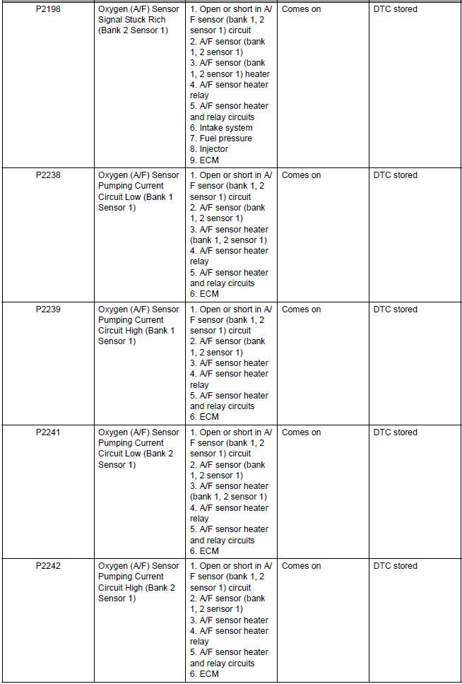
- Oxygen (A/F) Sensor Signal Stuck
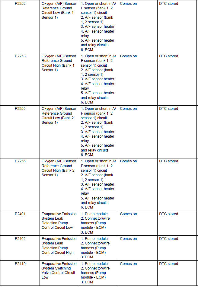
- Oxygen (A/F) Sensor Pumping Current Circuit
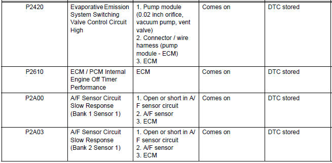
- Evaporative Emission System Switching Valve Control Circuit High
- ECM / PCM Internal Engine Off Timer Performance
- A/F Sensor Circuit Slow Response
- Active Control Engine Mount System
- EVAP System
- ECM Power Source Circuit
- VC Output Circuit
- Fuel Pump Control Circuit
- Cranking Holding Function Circuit
- ACIS Control Circuit
- Air Intake Control Circuit
- MIL Circuit
 Data list / active test
1. DATA LIST
HINT:
Reading the DATA LIST displayed on an intelligent tester
enables values, including those of the switches, sensors,
and actuators, to be checked without removing any
parts. Read ...
 Camshaft Position "A" Actuator Circuit
DTC P0010 Camshaft Position "A" Actuator Circuit (Bank
1)
DTC P0020 Camshaft Position "A" Actuator Circuit (Bank
2)
DESCRIPTION
The Variable Valve Timing (VVT) system includes ...
Other materials:
Catalyst System Efficiency Below Threshold
DTC P0420 Catalyst System Efficiency Below Threshold
(Bank 1)
DTC P0430 Catalyst System Efficiency Below Threshold
(Bank 2)
MONITOR DESCRIPTION
The ECM uses the sensors mounted in front of and behind the three-way
catalyst (TWC) to monitor its
efficiency. The first sensor, an Air Fuel ratio ...
Reassembly
1. INSTALL REAR WHEEL CYLINDER CUP KIT
(a) Temporarily tighten the bleeder plug to the wheel
cylinder, and install the bleeder plug cap.
(b) Apply lithium soap base glycol grease to the 2 new
wheel cylinder cups and the 2 pistons.
(c) Install the 2 wheel cylinder cups to each piston.
...
Rear Occupant Classification Sensor LH Collision
Detection
DTC B1787 Rear Occupant Classification Sensor LH Collision
Detection
DESCRIPTION
DTC B1787 is output when the occupant classification ECU receives a collision
detection signal sent by
the rear occupant classification sensor LH if an accident occurs.
DTC B1787 is also output when the front s ...
