Toyota Sienna Service Manual: Brake Warning Light Remains ON
DESCRIPTION
If the ECU detects a trouble, it turns on the brake warning light at the same time of prohibiting ABS control.
At this time, the ECU records a DTC in memory.
Connect terminals TC and CG of the DLC3 to make the brake warning light blink and output the DTC.
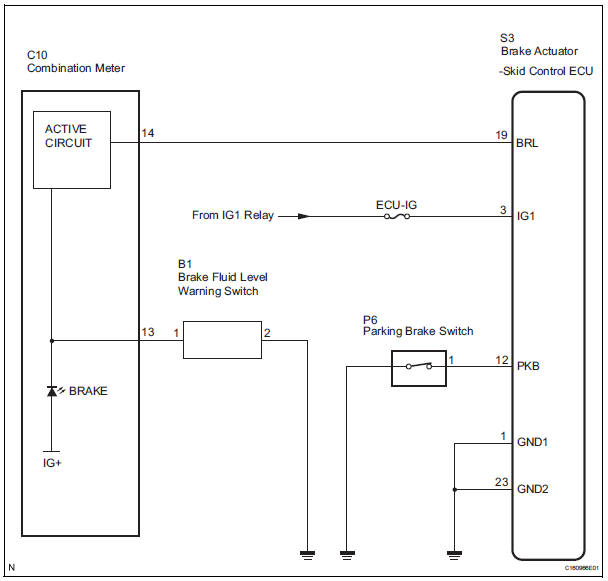
WIRING DIAGRAM
INSPECTION PROCEDURE
1 CHECK DTC
(a) Check if the ABS DTC is output (See page BC-10).
Result

2 INSPECT SKID CONTROL ECU CONNECTOR SECURELY CONNECTED
(a) Check the skid control ECU connector's connecting condition.
OK: The connector should be securely connected.

3 INSPECT BATTERY
(a) Check the battery voltage.
Standard voltage: 10 to 14 V

4 INSPECT SKID CONTROL ECU (IG1 TERMINAL VOLTAGE)
(a) Disconnect the skid control ECU connector.
(b) Turn the ignition switch to the on position.
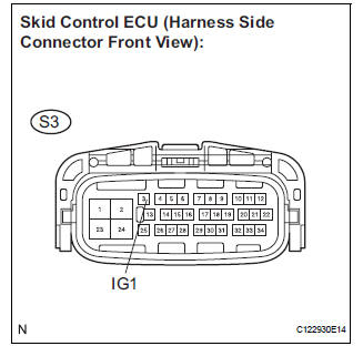
(c) Measure the voltage according to the value(s) in the table below.
Standard voltage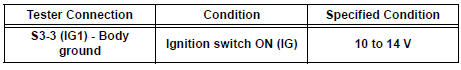

5 INSPECT SKID CONTROL ECU (GND TERMINAL CONTINUITY)
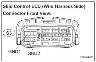
(a) Disconnect the skid control ECU connector.
(b) Measure the resistance according to the value(s) in the table below.
Standard resistance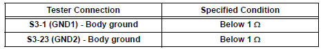

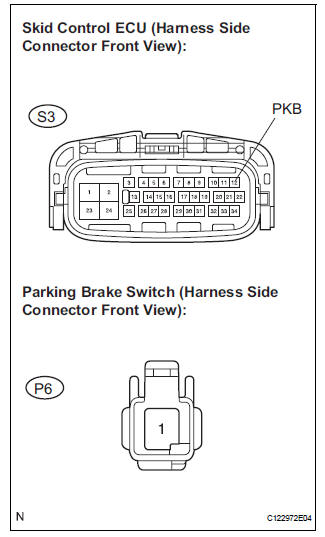
6 INSPECT PARKING BRAKE SWITCH
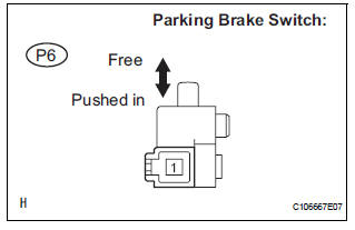
(a) Disconnect the parking brake switch connector.
(b) Measure the resistance according to the value(s) in the table below.
Standard resistance 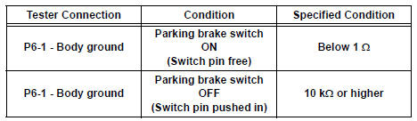

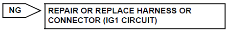
7 CHECK HARNESS AND CONNECTOR
(a) Disconnect the skid control ECU connector and parking brake switch.
(b) Measure the resistance according to the value(s) in the table below.
Standard resistance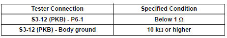

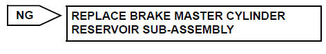
8 INSPECT BRAKE FLUID LEVEL WARNING SWITCH
(a) Remove the reservoir tank cap and strainer.
(b) Disconnect the brake fluid level warning switch connector.
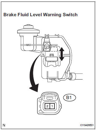
(c) Measure the resistance according to the value(s) in the table below.
HINT: A float is placed inside the reservoir. Its position can be changed by increasing/decreasing the level of brake fluid.
Standard resistance 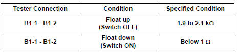
HINT: If there is no problem after finishing the above check, adjust the brake fluid level to the MAX level.

9 INSPECT HARNESS AND CONNECTOR (BETWEEN BRAKE FLUID LEVEL WARNING SW AND COMBINATION METER)
(a) Disconnect the combination meter connector.
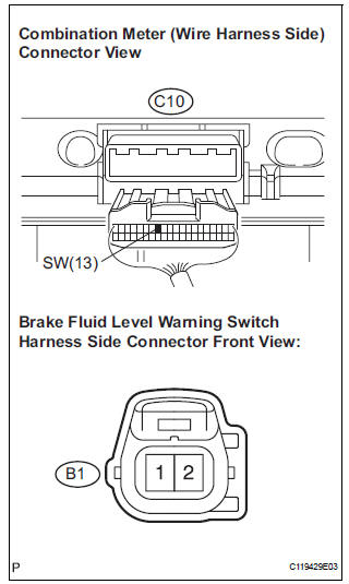
(b) Measure the resistance according to the value(s) in the table below.
Standard resistance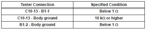

10 CHECK HARNESS AND CONNECTOR (BETWEEN SKID CONTROL ECU AND COMBINATION METER ASSEMBLY)
(a) Turn the ignition switch off.
(b) Disconnect the combination meter connector.
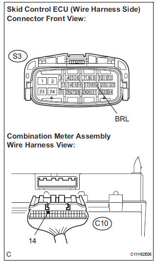
(c) Measure the resistance according to the value(s) in the table below.
Standard resistance 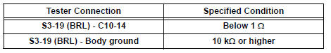

11 INSPECT COMBINATION METER ASSEMBLY
(a) Check the combination meter assembly (See page ME- 4).
HINT: If troubleshooting has been carried out according to the PROBLEM SYMPTOMS TABLE, refer back to the table and proceed to the next step before replacing the part (See page BC-7).

REPLACE BRAKE ACTUATOR ASSEMBLY
 ABS Warning Light does not Come ON
WIRING DIAGRAM
See page BC-47.
INSPECTION PROCEDURE
1 INSPECT ABS WARNING LIGHT
(a) Disconnect the skid control ECU connector.
(b) Turn the ignition switch to the ON position.
(c) Check that ...
 Brake Warning Light does not Come ON
WIRING DIAGRAM
See page BC-52.
INSPECTION PROCEDURE
1 INSPECT BRAKE WARNING LIGHT
(a) Disconnect the skid control ECU connector.
(b) Turn the ignition switch to the on position.
(c) Check th ...
Other materials:
Inspection
1. INSPECT GARAGE DOOR OPENER
Press the switch and check that each red LED turns
on. If one or more of the switches does not turn on
the LED, confirm normal operation of the fuse and
wire harness, then replace the garage door opener.
2. INSPECT GARAGE DOOR OPENER REGISTRATION ...
Installation
1. INSTALL COMBINATION METER ASSEMBLY
Connect the connectors.
Install the combination meter assembly with the 4
screws.
2. INSTALL INSTRUMENT CLUSTER FINISH PANEL SUB-ASSEMBLY
Install the instrument cluster finish panel subassembly
with the 4 clips.
3. C ...
How to proceed with
troubleshooting
HINT:
Use these procedures to troubleshoot the power door lock
control system.
The intelligent tester should be used in steps 4 and 5.
1 VEHICLE BROUGHT TO WORKSHOP
2 CUSTOMER PROBLEM ANALYSIS CHECK
HINT:
In troubleshooting, confirm that the problem symptoms
have ...
