Toyota Sienna Service Manual: Adjustment
1. REMOVE REAR WHEEL
2. ADJUST PARKING BRAKE SHOE CLEARANCE (See page PB-18)
3. INSTALL REAR WHEEL Torque: 103 N*m (1,050 kgf*cm, 76 ft.*lbf)
4. INSPECT PARKING BRAKE PEDAL TRAVEL
(a) Slowly depress the parking brake pedal all the way, and count the number of clicks.
Parking brake pedal travel: 3 to 5 clicks at 294 N (30 kgf, 66.0 lbf)
5. DISCONNECT BATTERY NEGATIVE TERMINAL
6. REMOVE FRONT DOOR SCUFF PLATE LH
7. REMOVE COWL SIDE TRIM BOARD LH (See page IP- 6)
8. REMOVE INSTRUMENT PANEL FINISH PANEL SUBASSEMBLY LOWER LH
9. ADJUST PARKING BRAKE PEDAL TRAVEL
(a) Depress the parking brake pedal 3 notches to make a room for the procedure, and loosen the lock nut.
(b) Return the parking brake pedal to the original position.
(c) Turn the adjusting nut until the parking brake pedal travel corrects.
(d) Depress the parking brake pedal 3 notches to make a room for the procedure, and tighten the lock nut.
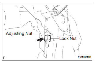
Torque: 5.4 N*m (55 kgf*cm, 48 in.*lbf)
(e) Return the parking brake pedal to the original position.
(f) Check whether the parking brake drags or not.
(g) When operating the parking brake pedal, check that the parking brake pedal indicator light goes on.
 Problem symptoms table
Use the table below to help you find the cause of the problem.
The numbers indicate the likelihood of the cause in the
descending order. Check each part in the order shown.
Replace these parts ...
 Parking brake pedal
Components
...
Other materials:
Adjustment procedure
Second seat
Tip-up seat (7-passenger models)
Seat position adjustment
lever
Seatback angle adjustment
lever
Tip-up seat (8-passenger models)
Seat position adjustment
lever
Seatback angle adjustment
lever
Ottoman seat
Seat position adjustment
...
Steering Pad Switch Circuit
DESCRIPTION
This circuit sends an operation signal from the steering pad switch to the
radio receiver.
If there is an open in the circuit, the audio system cannot be operated using
the steering pad switch.
If there is a short in the circuit, the same condition as that when the switch
is ...
How to proceed with
troubleshooting
1 VEHICLE BROUGHT TO WORKSHOP
2 INSPECT BATTERY VOLTAGE
Standard voltage:
11 to 14 V
If the voltage is below 11 V, recharge or replace the battery
before proceeding.
3 BASIC INSPECTION
Turn the ignition switch ON.
Check whether or not the radio receiver turns on.
Result
4 CHE ...
