Toyota Sienna Service Manual: Basic inspection
(a) WHEN MEASURING RESISTANCE OF ELECTRONIC PARTS
(1) Unless otherwise stated, all resistance measurements should be made at an ambient temperature of 20°C (68°F). Resistance measurements may be inaccurate if measured at high temperatures, i.e. immediately after the vehicle has been running. Measurements should be made after the engine has cooled down.
(b) HANDLING CONNECTORS
 HANDLING CONNECTORS
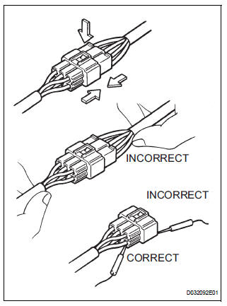
(1) When disconnecting a connector, first squeeze the mating connector housing halves tightly together to release the lock, and then press the lock claw and separate the connector.
(2) When disconnecting a connector, do not pull on the harnesses. Grasp the connector directly and separate it.
(3) Before connecting a connector, check that there are no deformations, damage, looseness or missing terminals.
(4) When connecting a connector, press firmly until it locks with a "click" sound.
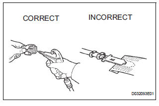
(5) If checking a connector with a TOYOTA electrical tester, check the connector from the backside (harness side) using a mini test lead.
• Do not damage the terminals by moving the inserted tester needle.
(c) CHECKING CONNECTORS
 CHECKING CONNECTORS
(1) Checking when a connectors is disconnected: Squeeze the connector together to confirm that they are fully connected and locked.
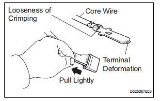
(2) Checking when a connector is disconnected: Check by pulling the wire harness lightly from the backside of the connector. Look for unlatched terminals, missing terminals, loose crimps or broken conductor wires. Check visually for corrosion, metallic or foreign matter and water, and bent, rusted, overheated, contaminated, or deformed terminals.
 Checking the contact pressure of the terminal
(3) Checking the contact pressure of the terminal: Prepare a spare male terminal. Insert it into a female terminal, and check for ample tension when inserting and after full engagement.
(d) REPAIR METHOD OF CONNECTOR TERMINAL
REPAIR METHOD OF CONNECTOR TERMINAL
(1) If there is any foreign matter on the terminal, clean the contact point with compressed air or a cloth. Never rub the contact point using sandpaper as the plating may come off.
(2) If there is abnormal contact pressure, replace the female terminal. If the male terminal is goldplated (gold color), use a gold-plated female terminal; if it is silver-plated (silver color), use a silver-plated female terminal.
(3) Damaged, deformed, or corroded terminals should be replaced. If the terminal does not lock into the housing, the housing may have to be replaced.
(e) HANDLING OF WIRE HARNESS
HANDLING OF WIRE HARNESS
(1) If removing a wire harness, check the wiring and clamping before proceeding so that it can be restored in the same way.
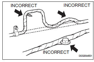
(2) Never twist, pull or slacken the wire harness more than necessary.
(3) The wire harness should never come into contact with a high temperature part, or rotating, moving, vibrating or sharp-edged parts. Avoid contact with panel edges, screw tips and other sharp items.
(4) When installing parts, never pinch the wire harness.
(5) Never cut or break the cover of the wire harness.
If it is cut or broken, replace it or repair it with vinyl tape.

 Check for open circuit
(a) For an open circuit in the wire harness in Fig. 1, the resistance or
voltage, as described below.
(b) Check the resistance.
Check the resistance
Standard resistance (Fig. 2)
...
Other materials:
Smart key system
The following operations can be performed simply by carrying
the electronic key on your person, for example in your pocket.
The driver should always carry the electronic key.
Locks and unlocks the doors
Front door handles
Sliding door handles
Back door
Starts and stops the ...
Installation
1. INSTALL POWER POINT SOCKET ASSEMBLY
Engage the 2 claws to install the power point socket
assembly.
2. INSTALL QUARTER TRIM FRONT PANEL ASSEMBLY
LH
3. INSTALL BACK DOOR SCUFF PLATE
4. INSTALL BACK DOOR WEATHERSTRIP
5. INSTALL REAR DOOR WEATHERSTRIP LH
6. INSTALL REAR DOOR S ...
CD Sound Skips
INSPECTION PROCEDURE
1 CHECK CD
Check the CD.
OK:
The CD is clean.
HINT:
If dirt is on the CD surface, wipe it clean with a soft cloth
from the inside to the outside in a radial direction.
NOTICE:
Do not use a conventional record cleaner or antistatic
preservative.
2 CHECK CD
...
