Toyota Sienna Service Manual: Reassembly
1. INSTALL FUEL PRESSURE REGULATOR ASSEMBLY
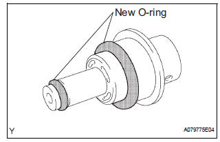
(a) Apply a light coat of gasoline or spindle oil to the 2 new O-rings, and install it to the fuel pressure regulator.
(b) Apply a light coat of gasoline or spindle oil to the 2 O-rings again, and install the fuel pressure regulator to the No. 1 fuel tube joint.
(c) Install the clip.
2. INSTALL FUEL PUMP HARNESS
3. INSTALL NO. 1 FUEL TUBE JOINT
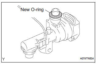
(a) Apply a light coat of gasoline or spindle oil to a new O- ring, and install it to the No. 1 fuel tube joint.
(b) Apply a light coat of gasoline or spindle oil to the Oring again, and install the No. 1 fuel tube joint to the fuel suction plate.
(c) Connect the connector.
4. INSTALL FUEL FILTER ASSEMBLY
(a) Install the fuel filter with a new clip.
5. INSTALL FUEL PUMP
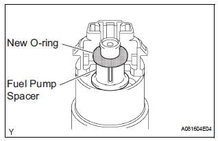
(a) Install the fuel pump spacer to the fuel pump.
(b) Apply a light coat of gasoline or spindle oil to a new O- ring, and install it to the fuel pump.
(c) Apply a light coat of gasoline or spindle oil to the Oring again, and install the fuel pump to the fuel suction plate.
(d) Connect the fuel pump connector.
6. INSTALL FUEL SUCTION PLATE SUB-ASSEMBLY
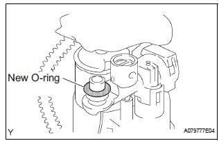
(a) Apply a light coat of gasoline or spindle oil to a new O- ring, and install it to the No. 1 fuel tube joint.
(b) Apply a light coat of gasoline or spindle oil to the Oring again, and install the fuel suction plate to the No. 1 fuel suction support.
7. INSTALL FUEL SENDER GAUGE ASSEMBLY
8. INSTALL FUEL SUCTION TUBE ASSEMBLY WITH PUMP AND GAUGE

| NOTICE: Prior to assembly, all the new components must be stabilized at room temperature for minimum 12 hours. |
(a) Ensure fuel suction tube set gasket groove is clean and free of foreign particles.
(b) Install a new fuel suction tube set gasket to the fuel tank.
(c) Make sure that the fuel suction tube set gasket sits in the groove.
(d) Align the arrow mark of the fuel suction tube assembly with pump and gauge and the tank suction tube support.
| NOTICE: Be careful not bend the arm of the fuel sender gauge. |
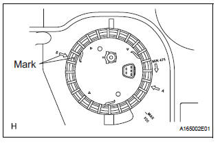
(e) Align marks on a new fuel pump gauge retainer and the fuel tank.
(f) Position the fuel pump gauge retainer on top of the fuel suction tube assembly with pump and gage flange while pushing down the flange on center.
(g) While holding the fuel suction tube assembly with pump and gauge, tighten the fuel pump gauge retainer one complete turn by hand.
NOTICE:
|
(h) Ensure that no cross threading occurred during installation by checking the gap between the fuel pump gauge retainer and the fuel tank. Confirm that the gap is even. If cross threading occurred, remove the fuel pump gauge retainer and repeat step (g).
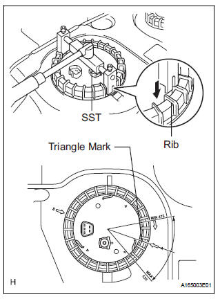
(i) Using SST, tighten the fuel pump gauge retainer to the specified torque.
SST 09808-14020 (09808-01410, 09808-01420, 09808-01430) Torque: 70 to 90 N*m (714 to 918 kgf*cm, 52 to 67 ft.*lbf)
NOTICE:
|
HINT:
A rib on the fuel pump gauge retainer can be fitted into a tip of the SST.
(j) Install the fuel pump gauge retainer by one and half turn so that the triangle mark on the fuel pump gauge retainer is between 475° and 535° from the start position.
(k) If the triangle mark is not reached 475°, confirm that no cross threading occurred by measuring the gap between the fuel pump gauge retainer and the fuel tank.
If cross threading occurred, replace the fuel pump gauge retainer, the gasket and the tank suction tube support.
(l) Replace the tank suction tube support.
(1) Remove the tank suction tube support from the fuel tank.
(2) Install the tank suction tube support to the fuel tank as shown in the illustration.
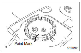
(m) Put a mark on the fuel pump gauge retainer and the fuel tank with paint. This will be the evidence that the fuel pump gauge retainer has been removed.
9. INSTALL FUEL TANK MAIN TUBE SUB-ASSEMBLY
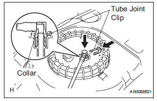
(a) Install in the fuel return tube with the tube joint clip.
NOTICE:
|
10. INSTALL FUEL TANK TO FILLER PIPE HOSE (See page FU-44)
 Inspection
1. INSPECT FUEL PUMP
(a) Inspect fuel pump resistance.
(1) Using an ohmmeter, measure the resistance
between the terminals.
Standard resistance
(b) Inspect fuel pump operation
(1) Apply ...
 Installation
1. INSTALL FUEL TANK ASSEMBLY (See page FU-44)V
2. INSPECT FOR FUEL LEAK (See page FU-7)
3. INSTALL FUEL TANK FILLER HOSE COVER (See
page FU-45)
4. INSTALL REAR FLOOR NO. 2 CROSSMEMBER
BRACE LH ( ...
Other materials:
Past record
Type A
Press the “CAR” button.
Type B
Press the “APPS” button, and then select “Eco” on the screen.
If the “Trip Information” screen is displayed, select “Past Record”.
Reset the past record data
Best recorded fuel consumption
Average fuel consumption ...
Trailer Tongue Weight
A recommended tongue weight varies in accordance with the types
of trailers or towing as described below.
To ensure the recommended values shown below, the trailer must
be loaded by referring to the following instructions.
Tongue Weight
The gross trailer weight should be distribute ...
Oil and oil filter
COMPONENTS
REPLACEMENT
CAUTION:
Prolonged and repeated contact with engine oil will
result in the removal of natural oils from the skin,
leading to dryness, irritation and dermatitis. In
addition, used engine oil contains potentially harmful
contaminants which may caus ...
