Toyota Sienna Service Manual: Removal
1. DISCHARGE FUEL SYSTEM PRESSURE HINT: See page FU-1.
2. DISCONNECT CABLE FROM NEGATIVE BATTERY TERMINAL
3. REMOVE NO. 1 ENGINE UNDER COVER
4. DRAIN ENGINE COOLANT (See page CO-6)
5. REMOVE FRONT WIPER ARM HEAD CAP (See page WW-4)
6. REMOVE FRONT WIPER ARM RH (See page WW-4)
7. REMOVE FRONT WIPER ARM LH (See page WW-4)
8. REMOVE COWL TOP VENTILATOR LOUVER SUBASSEMBLY (See page WW-4)
9. REMOVE WINDSHIELD WIPER MOTOR AND LINK ASSEMBLY (See page WW-4)
10. REMOVE NO. 1 COWL TOP TO COWL BRACE INNER
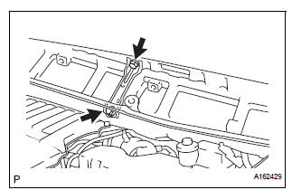
(a) Remove the 2 bolts and the No. 1 cowl top to cowl brace inner.
11. REMOVE COWL TOP PANEL SUB-ASSEMBLY OUTER FRONT
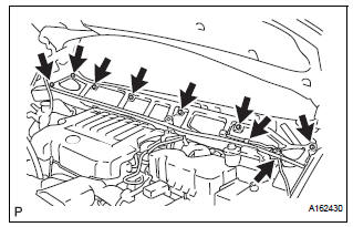
(a) Remove the wire harness clamp.
(b) Disconnect the fuel pump resistor connector.
(c) Remove the 7 bolts and the cowl top panel outer front.
12. REMOVE V-BANK COVER SUB-ASSEMBLY (See page EM-28)
13. REMOVE AIR CLEANER CAP SUB-ASSEMBLY
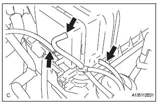
(a) Disconnect the 3 vacuum hoses.
(b) Remove the No. 2 ventilation hose and air cleaner hose band.
(c) Disconnect the vacuum hose (EVAP) from the air cleaner hose.
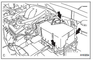
(d) Remove the 2 bolts and air cleaner cap subassembly.
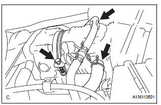
14. REMOVE INTAKE AIR SURGE TANK ASSEMBLY
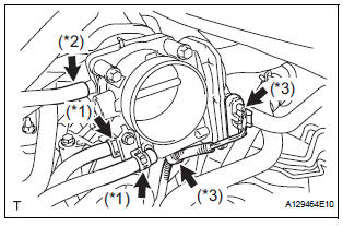
(a) Disconnect the 2 water by-pass hoses from the throttle with motor body assembly. (*1) (b) Disconnect the fuel vapor feed hose assembly.(*2) (c) Disconnect the throttle with motor body assembly connector and clamp. (*3)
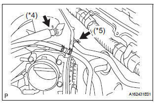
(d) Disconnect the No. 1 ventilation hose. (*4) (e) Disconnect the union to check valve hose. (*5)
(f) Disconnect the connector.
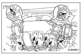
(g) Using a 5 mm socket hexagon wrench, remove the 4 bolts. (*1) (h) Remove the 2 nuts, 2 bolts, and intake air surge tank. (*2) (i) Remove the gasket from the intake air surge tank.
15. DISCONNECT FUEL TUBE SUB-ASSEMBLY
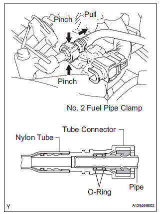
(a) Remove the No. 2 fuel pipe clamp.
(b) Pinch the tube connector and pull out the fuel pipe.
NOTICE:
|
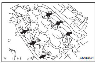
16. REMOVE FUEL INJECTOR ASSEMBLY
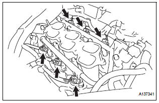
(a) Disconnect the 6 fuel injector connectors.
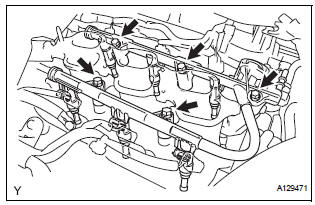
(b) Remove the 5 bolts and fuel delivery pipe subassembly together with the 6 fuel injectors.
| NOTICE: Be careful not to drop the fuel injectors when removing the fuel delivery pipe sub-assembly. |
(c) Remove the 6 injector vibration insulators from the intake manifold.
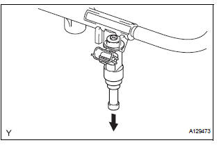
(d) Pull out the fuel injectors from the fuel delivery pipe sub-assembly
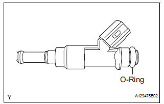
(e) Remove the 6 O-rings from the fuel injectors.
 Components
...
 Inspection
1. INSPECT FUEL INJECTOR ASSEMBLYV
(A) inspect the injector resistance.
(1) Using an ohmmeter, measure the resistance
between the terminals.
Standard resistance
If the resistance is not a ...
Other materials:
Installation
1. INSTALL BACK DOOR GLASS
Clean and shape the contact surface of the vehicle
body.
Using a knife, cut away any rough adhesive on
the contact surface of the body to ensure the
appropriate surface shape.
HINT:
Leave as much adhesive on the body as
possible.
& ...
ACIS Control Circuit
DESCRIPTION
This circuit opens and closes the Intake Air Control Valve (IACV) in response
to changes in the engine
load in order to increase the intake efficiency (ACIS: Acoustic Control
Induction System).
When the engine speed is between 0 and 4450 rpm and the throttle valve opening
angl ...
Read vin (vehicle identification number)
(a) The VIN reading process is shown in the flowchart
below. Reading the VIN stored in the ECM is
necessary when comparing it to the VIN provided
with the vehicle.
(b) Read the VIN using the intelligent tester.
(c) Check the vehicle's VIN.
(d) Connect the intelligent tester to the DLC3.
...
