Toyota Sienna Service Manual: Check for open circuit
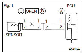
(a) For an open circuit in the wire harness in Fig. 1, the resistance or voltage, as described below.
(b) Check the resistance.
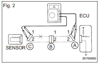
Check the resistance
Standard resistance (Fig. 2)
HINT:
Measure the resistance while lightly shaking the wire harness vertically and horizontally. If the results match the examples above, an open circuit exists between terminal 1 of connector A and terminal 1 of connector C.
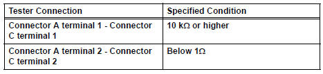
(2) Disconnect connector B and measure the resistance between the terminals of the connectors.
Standard resistance (Fig. 3)
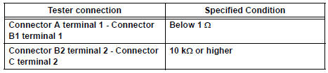
If the results match the examples above, an open circuit exists between terminal 1 of connector B2 and terminal 1 of connector C.
(c) Check the voltage.
Check the voltage
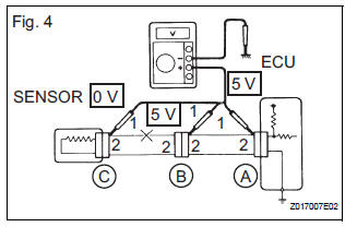
(1) In a circuit in which voltage is applied to the ECU connector terminal, an open circuit can be checked by conducting a voltage check.
With each connector still connected, measure the voltage between the body ground and these terminals (in this order): 1) terminal 1 of connector A, 2) terminal 1 of connector B, and 3) terminal 1 of connector C.
Standard voltage (Fig. 4)
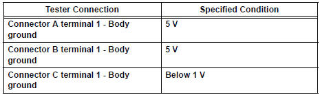
If the results match the examples above, an open circuit exists in the wire harness between terminal 1 of connector B and terminal 1 of connector C.
 Basic inspection
(a) WHEN MEASURING RESISTANCE OF
ELECTRONIC PARTS
(1) Unless otherwise stated, all resistance
measurements should be made at an ambient
temperature of 20°C (68°F). Resistance
measurements may b ...
 Check for short circuit
(a) If the wire harness is ground shorted (Fig. 5), locate the section by
conducting a resistance check with the body ground (below).
(b) Check the resistance with the body ground.
...
Other materials:
Installation
1. INSTALL CENTER REAR SEAT LAP TYPE BELT
ASSEMBLY (for 8-Passenger)
HINT:
Refer to the instructions for reassembly of the rear No. 1 seat assembly (for
center seat).
Install the center rear seat lap type belt assembly
with the bolt.
Torque: 42 N*m (430 kgf*cm, 31 ft.*lbf)
2. I ...
Situations when it is necessary to contact dealers before towing
The following may indicate a problem with your transaxle. Contact
your Toyota dealer or commercial towing service before towing.
The engine is running but the vehicle does not move.
The vehicle makes an abnormal sound
Towing with a sling-type truck
Do not tow with a sling-type truck
to p ...
Reassembly
1. INSTALL INSTR PNL PASS L/DOOR AIR BAG
ASSEMBLY
2. INSTALL INSTRUMENT PANEL WIRE NO.2
3. INSTALL NAVIGATION ANTENNA ASSEMBLY
4. INSTALL ANTENNA CORD SUB-ASSEMBLY
5. INSTALL INSTRUMENT PANEL BOX DOOR SUBASSEMBLY
NO.2
6. INSTALL INSTRUMENT PANEL FINISH PANEL
RETAINER NO.1
7. INSTALL INSTRUM ...
