Toyota Sienna Service Manual: Brake
GENERAL MAINTENANCE
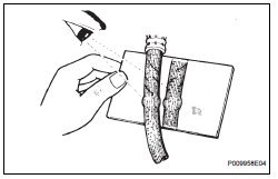
1. INSPECT BRAKE LINE PIPES AND HOSES
HINT:
Check the entire circumference and length of the brake hoses using a mirror as required in a well-lighted area.
Turn the front wheels fully right or left before checking the front brakes.
(a) Check all the brake lines and hoses for:
- Damage
- Wear
- Deformation
- Cracks
- Corrosion
- Leaks
- Bends
- Twists
(b) Check all the clamps for tightness and connections for leakage.
(c) Check that the hoses and lines are clear of sharp edges, moving parts and the exhaust system.
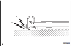
(d) Check that the lines are installed in grommets passing through the center of the grommets.
2. INSPECT FRONT BRAKE PADS AND DISCS
HINT:
(See page BR-26)
(a) If a squealing or scraping noise is heard from the brakes while driving, check the pad wear indicator.
If there are traces of the indicator contacting
3. INSPECT REAR BRAKE PADS AND DISCS
HINT:
(See page BR-32)
4. REMOVE REAR BRAKE LININGS AND DRUMS
HINT:
(See page BR-39)
 Engine
GENERAL MAINTENANCE
HINT:
Inspect these items when the engine is cold.
1. INSPECT DRIVE BELT
HINT:
(See page EM-6)
2. REPLACE SPARK PLUGS
HINT:
(See page IG-8)
3. INSPECT AIR FILTER
(a) ...
 Chassis
GENERAL MAINTENANCE
1. INSPECT STEERING LINKAGE
(a) Check the steering linkage for looseness or
damage.
Check that:
Tie rod ends do not have excessive play.
Dust seals and boots are not da ...
Other materials:
Taking out the jack and tools
Remove the cover.
Remove the adapter socket.
Remove the jack.
Remove the wheel nut wrench.
...
Skid Control Buzzer Circuit
DESCRIPTION
The skid control buzzer sounds and SLIP indicator blinking during VSC
operation.
WIRING DIAGRAM
INSPECTION PROCEDURE
1 PERFORM ACTIVE TEST USING INTELLIGENT TESTER (SKID CONTROL BUZZER)
(a) Connect the intelligent tester to the DLC3.
(b) Start the engine.
(c) Select the ...
Approach warning
When your vehicle is too close to a vehicle ahead, and sufficient automatic
deceleration via the cruise control is not possible, the display
will flash and the buzzer will sound to alert the driver. An example of
this would be if another driver cuts in front of you while you are following
a vehi ...
