Toyota Sienna 2010-2026 Owners Manual: Calibrating the compass
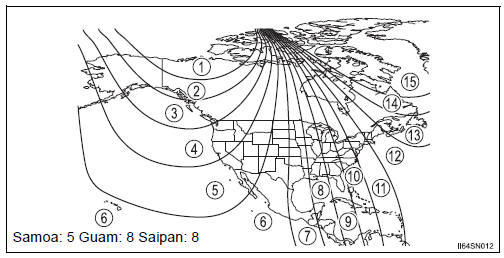
The direction display deviates from the true direction determined by the earth’s magnetic field. The amount of deviation varies according to the geographic position of the vehicle.
If you cross over a map boundary shown in illustration, the compass will deviate.
To obtain higher precision or perfect calibration, refer to the following.
Deviation calibration
- Stop the vehicle where it is safe to drive in a circle.
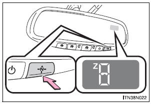
- Press and hold the switch.
A number (1 to 15) appears on the compass display.
- Referring to the map above, press the switch to select the number
of the zone you are in.
If the direction is displayed several seconds after adjustment, the calibration is complete.
Circling calibration
When “C” appears on the display, drive the vehicle at 5 mph (8 km/h) or less in a circle until a direction is displayed.
If there is not enough space to drive in a circle, drive around the block until the direction is displayed.
Conditions unfavorable to correct operation
The compass may not show the correct direction in the following conditions:
- The vehicle is stopped immediately after turning.
- The vehicle is on an inclined surface.
- The vehicle is in a place where the earth’s magnetic field is subject to interference by artificial magnetic fields (underground car park/parking lot, under a steel tower, between buildings, roof car park/parking lot, near an intersection, near a large vehicle, etc.).
- The vehicle has become magnetized.
(There is a magnet or metal object near the inside rear view mirror.)
- The battery has been disconnected.
- A door is open.
| WARNING While driving the vehicle Do not adjust the display. Adjust the display only when the vehicle is stopped. When doing the circling calibration Secure a wide space, and watch out for people and vehicles in the vicinity. Do not violate any local traffic rules while performing circling calibration. |
| NOTICE To avoid compass malfunctions Do not place magnets or any metal objects near the inside rear view mirror. Doing this may cause the compass sensor to malfunction. To ensure normal operation of the compass
|
 Operation
To turn the compass on or off,
press the switch.
Displays and directions
...
 Safety Connect
Safety Connect is a subscription-based telematics service that
uses Global Positioning System (GPS) data and embedded cellular
technology to provide safety and security features to subscribers.
S ...
Other materials:
Installation
HINT:
Install the RH side by the same procedure as the LH side.
1. INSTALL REAR SPEED SENSOR
(a) Clean the contacting surface of the axle hub and a
new skid control sensor.
NOTICE:
Keep the sensor rotor clean.
(b) Place the speed sensor on the axle hub so that the
connector is positioned ...
Short in Driver Side Squib Circuit
DTC B0100/13 Short in Driver Side Squib Circuit
DESCRIPTION
The driver side squib circuit consists of the center airbag sensor assembly,
the spiral cable and the
steering pad. The circuit instructs the SRS to deploy when deployment conditions
are met. DTC B0100/13
is recorded when a short ci ...
Sensor detection display, obstacle distance
Distance display
Sensors that detect an obstacle will illuminate continuously or blink.
*1: The images may differ from that shown in the illustrations.
*2: Multi-information display
*3: Audio system screen
Buzzer operation and distance to an obstacle
A buzzer sounds when the sensors are o ...
