Toyota Sienna Service Manual: Cruise Main Indicator Light Circuit
DESCRIPTION
When the cruise control main switch is on, the CRUISE main indicator light and READY indicator light come on. This indicates the control condition (presence or absence of a vehicle in front, vehicle-to-vehicle distance, and set vehicle speed) and fail-safe state through the multiplex communication system. The master warning light and CRUISE main indicator light come on and vehicle-to-vehicle distance information is displayed on the combination meter as the alarm buzzer sounds.
HINT: If the vehicle in front in the same lane significantly decreases vehicle speed or another vehicle cuts in front of your vehicle, adequate deceleration cannot be applied and the vehicle-to-vehicle distance will shorten. At this time, the system sounds the buzzer and the multi-information display blinks to warn the driver.
INSPECTION PROCEDURE
1 PERFORM ACTIVE TEST BY INTELLIGENT TESTER
- Connect the intelligent tester to the DLC3.
- Select the ACTIVE TEST, use the intelligent tester to generate a control command, and then check that the CRUISE main indicator light blinks.
METER:

OK: Indicator light blinks/goes off.
2 READ VALUE OF INTELLIGENT TESTER
- Connect the intelligent tester to the DLC3.
- Turn the ignition switch to the ON position, and turn the intelligent tester main switch on.
- Check the DATA LIST for proper functioning of the CRUISE main indicator light.
ECM (Cruise control):
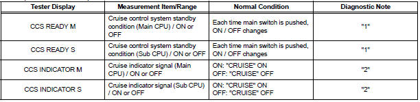
OK: When the cruise control main switch is operated, the display changes as shown above.
HINT: "1" is OK, but "2" is NG → DTC output or ECM failure
PROCEED TO NEXT CIRCUIT INSPECTION SHOWN IN PROBLEM SYMPTOMS TABLE
 Washer Signal Circuit
DESCRIPTION
The distance control ECU detects washer operation. The cruise control will be
cancelled by the distance
control ECU if the windshield wipers operate in the HI or LO mode. By detecting ...
 TC and CG Terminal Circuit
DESCRIPTION
Connecting terminals TC and CG of the DLC3 causes the system to enter the
self-diagnostic mode. If a
malfunction is present, DTCs will be output.
HINT:
When a particular warning ligh ...
Other materials:
Rear power window switch
INSPECTION
1. INSPECT POWER WINDOW REGULATOR SWITCH ASSEMBLY REAR
Check the resistance between the switch terminals
when the switch is operated.
Standard
If the result is not as specified, replace the switch
assembly. ...
Dtc check / clear
1. DTC CHECK/CLEAR (WHEN USING INTELLIGENT TESTER):
(a) DTC check
(1) Connect the intelligent tester to the DLC3.
(2) Turn the ignition switch to the ON position.
(3) Read the DTCs following the prompts on the
tester screen.
(b) DTC clear
(1) Connect the intelligent tester to the DLC3 ...
Problem symptoms table
Use the table below to find the cause of the problem. The
numbers indicate the priority of the likely cause of the
problem. Check each part in order. If necessary, replace
these parts.
Front A/C:
Rear A/C:
...
