Toyota Sienna Service Manual: Check and replace ecu
• When no measuring condition is specified, perform the inspection with the engine stopped and the ignition switch on.
• Check that the connectors are fully seated. Check for loose, corroded or broken wires.
(a) First, check the ECU ground circuit. If it is faulty, repair it. If it is normal, the ECU could be faulty.
Temporarily replace the ECU with a normally functioning one and check if the symptoms occur. If the trouble symptoms disappear, replace the original ECU.
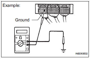
(1) Measure the resistance between the ECU ground terminal and body ground.
Standard resistance: Below 1 Ω
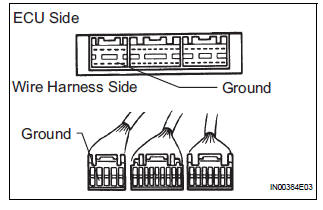
(2) Disconnect the ECU connector. Check the ground terminal on the ECU side and wire harness side for bending, corrosion or foreign matter. Lastly, check the contact pressure of the female terminals.
 Check for short circuit
(a) If the wire harness is ground shorted (Fig. 5), locate the section by
conducting a resistance check with the body ground (below).
(b) Check the resistance with the body ground.
...

Other materials:
Removal
NOTICE:
Do not adjust the brake booster push rod.
Do not change the combination of the diameter
converting unit and brake.
1. REMOVE FRONT WHEEL
2. DRAIN BRAKE FLUID
NOTICE:
Wash the brake fluid off immediately if it attaches to
any painted surfaces.
3. SEPARATE BATTERY NEGATIVE TERM ...
Player Error
DTC 58-44 Player Error
DTC 80-44 Player Error
DESCRIPTION
DTC No.
DTC Detection Condition
Trouble Area
58-44
Map player error is detected
Radio and navigation assembly
80-44
Map player error is detected.
INSPECTION PROCEDURE
HINT: ...
Disassembly
1. REMOVE OIL PUMP RELIEF VALVE
(A) using a 27 mm socket wrench, remove the relief
valve plug.
(B) remove the valve spring and oil pump relief valve.
2. REMOVE OIL PUMP COVER
(a) Remove the 8 bolts, oil pump cover and oil pump
rotor set. ...
