Toyota Sienna Service Manual: Pressure Control Solenoid "D" Electrical (Shift Solenoid Valve SLT)
DESCRIPTION
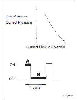
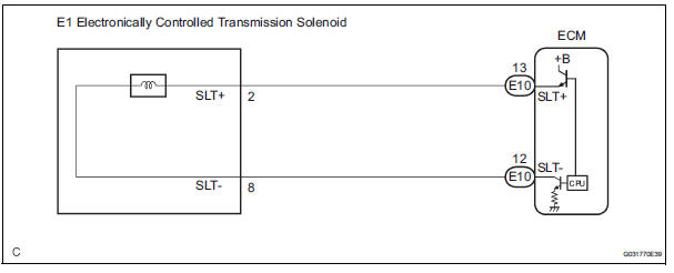
The linear solenoid valve (SLT) controls the transmission line pressure for smooth transmission operation based on signals from the throttle position sensor and the vehicle speed sensor. The ECM adjusts the duty cycle of the SLT solenoid valve to control hydraulic line pressure coming from the primary regulator valve. Appropriate line pressure assures smooth shifting with varying engine outputs.
(*): Duty Ratio The duty ratio is the ratio of the period of continuity in one cycle.
For example, if A is the period of continuity in one cycle, and B is the period
of non-continuity, then
Duty Ratio = A/(A + B) x 100(%)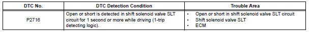
MONITOR DESCRIPTION
When an open or short in the linear solenoid valve (SLT) circuit is detected, the ECM interprets this as a fault. The ECM will turn on the MIL and store the DTC.
MONITOR STRATEGY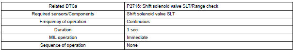
TYPICAL ENABLING CONDITIONS
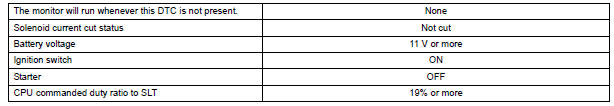
TYPICAL MALFUNCTION THRESHOLDS

COMPONENT OPERATING RANGE

WIRING DIAGRAM
INSPECTION PROCEDURE
1 INSPECT TRANSMISSION WIRE (SLT)
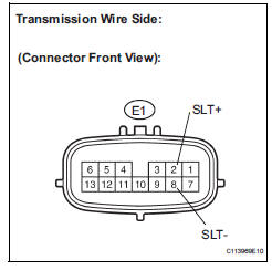
(a) Disconnect the transmission wire connector from the transaxle.
(b) Measure the resistance according to the value(s) in the table below.
Standard resistance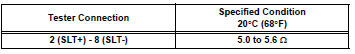
(c) Measure the resistance according to the value(s) in the table below.
Standard resistance (Check for short)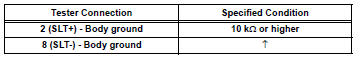

2 CHECK HARNESS AND CONNECTOR (TRANSMISSION WIRE - ECM)
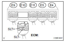
(a) Connect the transmission wire connector to the transaxle.
(b) Disconnect the ECM connector.
(c) Measure the resistance according to the value(s) in the table below.
Standard resistance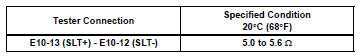
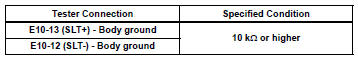
(d) Measure the resistance according to the value(s) in the table below.
Standard resistance (Check for short)

REPLACE ECM
3 INSPECT SHIFT SOLENOID VALVE SLT
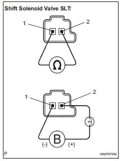
(a) Remove the shift solenoid valve (SLT).
(b) Measure the resistance according to the value(s) in the table below.
Standard resistance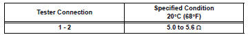
(c) Connect the positive (+) lead with a 21 W bulb to terminal 2 and the negative (-) lead to terminal 1 of the solenoid valve connector, then check the movement of the valve.
OK: The solenoid makes an operating sound.

REPAIR OR REPLACE TRANSMISSION WIRE
 Pressure Control Solenoid "D" Performance (Shift
Solenoid Valve SLT)
Pressure Control Solenoid "D" Performance (Shift
Solenoid Valve SLT)
SYSTEM DESCRIPTION
The linear solenoid valve (SLT) controls the transmission line pressure for
smooth transmission operation
based on signals from the throttle position sensor and the vehicle spee ...
 Torque Converter Clutch Solenoid Circuit
DESCRIPTION
The shift solenoid valve DSL is turned "ON" and "OFF" by signals from the ECM
in order to control the
hydraulic pressure operation, the lock-up relay valve, whi ...
Other materials:
Meter panel light control
The brightness of the meter panel lights can be adjusted.
Pressing the button will adjust the
brightness of the meter panel
lights.
The brightness level of the meters
when the surroundings are bright
(day mode) and dark (night mode)
can be adjusted individually. However,
when in day ...
DTC check / clear
1. CHECK DTC
Connect the intelligent tester to the DLC3.
Connect the intelligent tester to the Controller
Area Network Vehicle Interface Module (CAN
VIM). Then connect the CAN VIM to the Data
Link Connector 3 (DLC3).
Turn the ignition switch to the ON posi ...
Open in Driver Side Squib Circuit
DTC B0101/14 Open in Driver Side Squib Circuit
DESCRIPTION
The driver side squib circuit consists of the center airbag sensor assembly,
the spiral cable and the
steering pad.
The circuit instructs the SRS to deploy when deployment conditions are met.
DTC B0101/14 is recorded when an open ...
