Toyota Sienna Service Manual: System description
1. MULTIPLEX COMMUNICATION SYSTEM (BEAN)
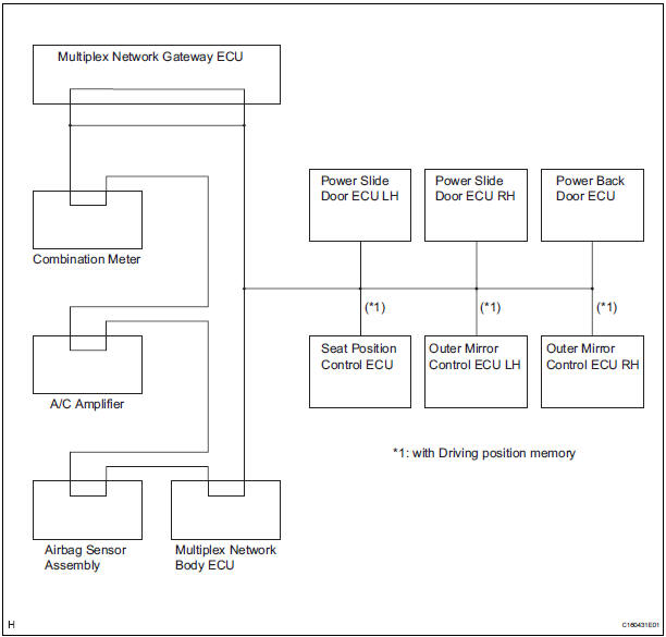
- The BEAN communication line is used to control the combination meter, the A/C amplifier, the airbag sensor assembly, the multiplex network body ECU, the power slide door ECU LH, the power slide door ECU RH, the power back door ECU, the seat position control ECU, the outer mirror control ECU LH, and the outer mirror ECU RH. If there is a shortcircuit (bus-down) in the line, the communication to the system that has a short-circuit (bus-down) will be disabled and the DTC concerning the system will be output from the multiplex network gateway ECU.
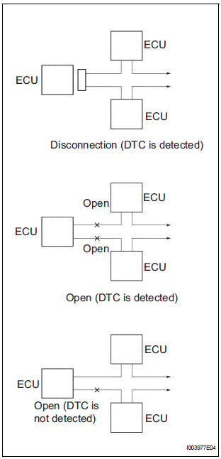
- If the DTC of ECU communication stop is output, connectors may be disconnected, or communication buses may be open at 2 points. It will not become abnormal with only 1 communication bus open.
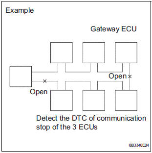
- If 2 communication buses are open at the points shown in the illustration, the DTC of ECU communication stop between those 2 buses is output.
2. CHECK COMMUNICATION FUNCTION
- Check the battery voltage.
Standard voltage: 11 to 14 V
- Inspect the DTC output.
- Check a DTC concerning the multiplex network body ECU by connecting the intelligent tester to the DLC3 and turning the ignition switch to the ON position.
- When the display shows DTCs concerning the ECU unconnected and the communication bus defective, perform the inspection depending on the troubleshooting procedures.
HINT: When another DTC is output, refer to the DTC table and check the applicable section.
 Multiplex communication system
PARTS LOCATION
...
 How to proceed with
troubleshooting
How to proceed with
troubleshooting
HINT:
Troubleshoot in accordance with the procedures on the
following pages.
1 VEHICLE BROUGHT TO WORKSHOP
2 DTC CHECK
Check for DTCs and make a note of the code that is
output (See page MP- ...
Other materials:
On-vehicle inspection
HINT:
The type of ignition switch on this model differs according to
the specifications of the vehicle. For the expressions used in
this section, refer to the "EXPRESSIONS OF IGNITION
SWITCH" precaution (See page ES-1).
1. CHECK AIR FUEL RATIO COMPENSATION SYSTEM
(a) Connect the inte ...
Screen Flicker or Color Distortion
INSPECTION PROCEDURE
1 CHECK DISPLAY SETTING
Enter the display adjustment screen by pressing the
"DISPLAY" switch.
Reset display settings (contrast, brightness) and check
that the screen appears normal
Press the "INFO" switch and then select "S ...
DTC check / clear
1. DTC CHECK (USING SST CHECK WIRE)
Check the DTCs (Present trouble code).
Turn the ignition switch ON, and wait for
approximately 60 seconds.
Using SST, connect terminals TC and CG of the
DLC3.
SST 09843-18040
NOTICE:
Connect the terminals to the correct
positi ...
