Toyota Sienna Service Manual: Check for short circuit
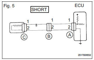
(a) If the wire harness is ground shorted (Fig. 5), locate the section by conducting a resistance check with the body ground (below).
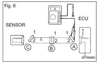
(b) Check the resistance with the body ground.
(1) Disconnect connectors A and C and measure the resistance.
Standard resistance (Fig. 6)
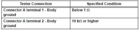
HINT:
Measure the resistance while lightly shaking the wire harness vertically and horizontally. If your results match the examples above, an open circuit exists between terminal 1 of connector A and terminal 1 of connector C.
(2) Disconnect connector B and measure the resistance.
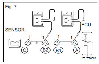
Standard resistance (Fig. 7)
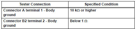
If the results match the examples above, a short circuit exists between terminal 1 of connector B2 and terminal 1 of connector C.
 Check for open circuit
(a) For an open circuit in the wire harness in Fig. 1, the resistance or
voltage, as described below.
(b) Check the resistance.
Check the resistance
Standard resistance (Fig. 2)
...
 Check and replace ecu
NOTICE: • The connector should not be disconnected from
the ECU. Perform the inspection from the
backside of the connector on the wire harness
side.
• When no measuring condition is s ...
Other materials:
Engine Coolant Temperature / Intake Air Temperature Correlation
DESCRIPTION
The ECM calculates the difference between the readings of the coolant
temperature sensor and intake air
temperature sensor. If the difference is greater than 20°C (68°F), the ECM will
judge this as a malfunction
and will set this DTC.
HINT:
Waiting is required t ...
Meter Illumination does not Dim at Night
DESCRIPTION
Confirm that the vehicle is equipped with the optitron meter, then
check this circuit.
The combination meter assembly receives a auto dimmer signal from
the body ECU by the multiplex
communication line.
WIRING DIAGRAM
INSPECTION PROCEDURE
1 CHECK MULTIP ...
Ignition Coil Primary / Secondary Circuit
DTC P0351 Ignition Coil "A" Primary / Secondary Circuit
DTC P0352 Ignition Coil "B" Primary / Secondary Circuit
DTC P0353 Ignition Coil "C" Primary / Secondary Circuit
DTC P0354 Ignition Coil "D" Primary / Secondary Circuit
DTC P0355 Ignition Coil "E& ...
