Toyota Sienna Service Manual: Data list / active test
1. READ DATA LIST
HINT: Using the intelligent tester to read the Data List allows the values or states of switches, sensors, actuators and other items to be read without removing any parts. This non-intrusive inspection can be very useful because intermittent conditions or signals may be discovered before parts or wiring is disturbed. Reading the Data List information early in troubleshooting is one way to save diagnostic time.
- Connect the intelligent tester to the DLC3.
- Turn the ignition switch to the ON position.
- Read the DATA LIST according to the display on the tester.
LASER CRUISE:
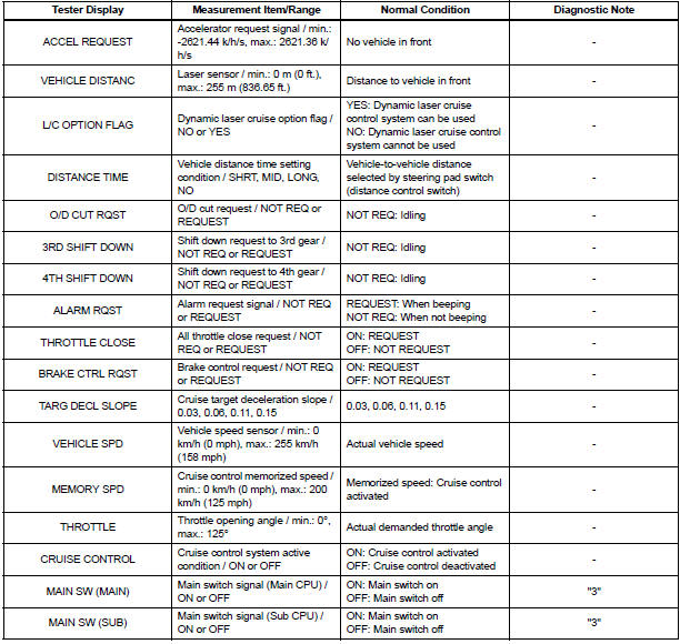
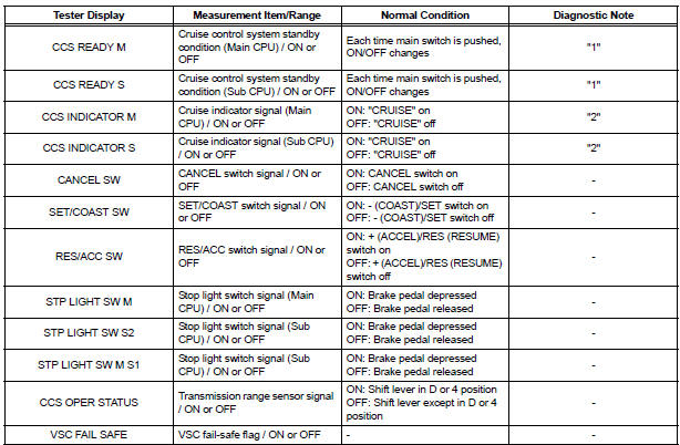
HINT: "3" is OK, but "1" is NG → ECM failure "1" is OK, but "2" is NG → DTC output or ECM failure "3" is OK, but cruise indicator does not turn on → Indicator, wire harness, or ECM failure
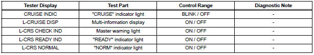
2. ACTIVE TEST
HINT: Using the intelligent tester to perform Active Tests allows relays, VSVs, actuators and other items to be operated without removing any parts. This non-intrusive functional inspection can be very useful because intermittent operation may be discovered before parts or wiring is disturbed. Performing Active Tests early in troubleshooting is one way to save diagnostic time. Data List information can be displayed while performing Active Tests.
- Connect the intelligent tester to the DLC3.
- Turn the ignition switch to the ON position.
- According to the display on the tester, perform the "ACTIVE TEST".
HINT: The ignition switch must be turned to the ON position to proceed with the Active Test using an intelligent tester.
ABS/TRAC/VSC:

METER:
 Fail-safe chart
1. AUTO CANCEL FUNCTION (FAIL-SAFE FUNCTION):
HINT:
If a system malfunction occurs, the applicable DTCs will
appear on the multi-information display. In some cases,
a DTC will be set due to we ...
 Diagnostic trouble code chart
If a trouble code is displayed during the DTC check, check
the trouble areas listed for that code in the table below and
proceed to the appropriate page.
Dynamic Laser Cruise Control System:
...
Other materials:
Bluetooth Module Initialization Failed
DTC 57-47 Bluetooth Module Initialization Failed
DESCRIPTION
DTC No.
DTC Detection Condition
Trouble Area
57-47
Bluetooth module is not installed.
Problem with Bluetooth module
Problem in communication line to Bluetooth module
...
Standard bolt
HOW TO DETERMINE BOLT STRENGTH
SPECIFIED TORQUE FOR STANDARD BOLTS
HOW TO DETERMINE NUT STRENGTH
HINT:
*: Nut with 1 or more marks on one side surface of the nut.
Use a nut with the same nut strength classification number
(or greater) as the bolt strength classification number ...
Air Intake Control Circuit
DESCRIPTION
The air cleaner is equipped with two inlets, one of which is opened or closed
by the Air Intake Control
Valve (AICV). This system reduces intake noise and increases engine power at
low-to-high engine speed
range.
When the engine is operating in the low-to-mid speed range, this ...
