Toyota Sienna Service Manual: ECM / PCM Processor

DESCRIPTION
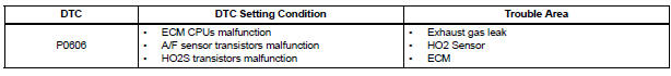
The ECM continuously monitors its internal processors (CPUs), A/F sensor transistors and heated oxygen sensor (HO2S) transistors. This self-check ensures that the ECM is functioning properly. These are diagnosed by internal "mirroring" of the main and sub CPUs to detect the processors error. If outputs from the processors deviate from the standards, the ECM will illuminate the MIL and set a DTC immediately.
MONITOR STRATEGY
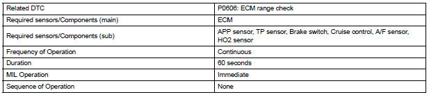
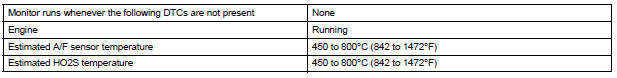
TYPICAL ENABLING CONDITIONS
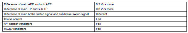
TYPICAL MALFUNCTION THRESHOLDS
INSPECTION PROCEDURE
1 INSPECT FOR EXHAUST GAS LEAK
(a) Allow the engine to idle.
(b) Check for exhaust gas leak around the heated oxygen sensor.
OK: No leak from the heated oxygen sensor.


2 CHECK HEATED OXYGEN SENSOR
(a) Connect the intelligent tester to the DLC3.
(b) Start the engine and turn the tester on.
(c) Warm up the engine at an engine speed of 2500rpm for approximately 90 seconds.
(d) Enter the following menus: DIAGNOSIS / ENHANCED II / ACTIVE TEST / A/F CONTROL.
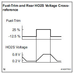
(e) Perform the A/F CONTROL operation with the engine in an idling condition (press the RIGHT or LEFT button to change the fuel injection volume).
(f) Monitor the voltage outputs of the HO2 sensors (O2S B1S2) displayed on the tester.
HINT:
- The A/F CONTROL operation lowers the fuel injection volume by 12.5% or increases the injection volume by 25%.
- Each sensor reacts in accordance with increases in the fuel injection volume.
Standard voltage 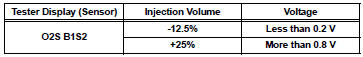
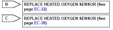
Result 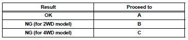

3 CHECK WHETHER DTC OUTPUT RECURS (IN ADDITION TO DTC P0606)
(a) Connect the intelligent tester to the DLC3.
(b) Turn the ignition switch to the ON position.
(c) Turn the tester on.
(d) Clear the DTC.
(e) Turn the ignition switch off.
(f) Disconnect the battery negative terminal and wait for 1 minute.
(g) Connect the battery negative terminal.
(h) Start the engine.
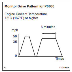
(i) Perform the drive pattern.
(1) Warm up the engine.
(2) Accelerate the vehicle to 50 mph (80 km/h) and stop the vehicle.
(3) Drive the vehicle at 35 to 50 mph (60 to 80 km/h) for 5 minutes or more.
(j) Enter the following menus: DIAGNOSIS / ENHANCED II / DTC INFO / CURRENT CODES.
(k) Read the DTCs.
Result 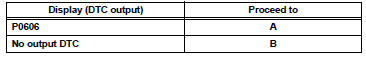

REPLACE ECM (See page ES-498)
 Internal Control Module Random Access Memory (RAM) Error
DESCRIPTION
The ECM continuously monitors its own internal memory status, internal
circuits, and output signals
transmitted to the throttle actuator. This self-check ensures that the ECM is
...
 Control Module Performance
DESCRIPTION
The ECM continuously monitors its main and sub CPUs. This self-check ensures
that the ECM is
functioning properly. If outputs from the CPUs are different and deviate from
the sta ...
Other materials:
Trouble in Passenger Airbag ON / OFF Indicator
DESCRIPTION
The occupant classification system detects the front passenger seat
condition. It then informs a
passenger of the front passenger airbag, the front seat side airbag RH and front
seat belt pretensioner
RH condition (activated/not activated) by the passenger airbag ON/OFF indicator. ...
Replacing a flat tire
Chock the tires.
Slightly loosen the wheel nuts
(one turn).
Turn the tire jack portion A by
hand until the notch of the jack
is in contact with the jack point.
The jack point guides are located
on the side of rocker moulding.
They indicate the jack point po ...
Removal
HINT:
Use the same procedures for the RH side and LH side.
The procedures listed below are for the LH side.
1. PRECAUTION
CAUTION:
Be sure to read "PRECAUTION" thoroughly before
servicing.
2. DISCONNECT CABLE FROM NEGATIVE BATTERY
TERMINAL
CAUTION:
Wait for 90 s ...
