Toyota Sienna Service Manual: Installation
1. INSTALL COMBINATION METER ASSEMBLY
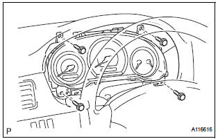
- Connect the connectors.
- Install the combination meter assembly with the 4 screws.
2. INSTALL INSTRUMENT CLUSTER FINISH PANEL SUB-ASSEMBLY
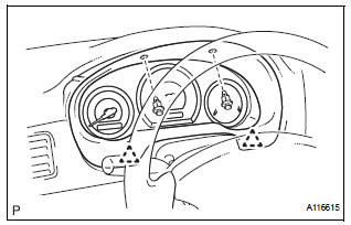
- Install the instrument cluster finish panel subassembly with the 4 clips.
3. CONNECT CABLE TO NEGATIVE BATTERY TERMINAL
4. PERFORM INITIALIZATION
- Perform initialization.
NOTICE: Some systems need initialization when disconnecting the cable from the negative battery terminal.
 Removal
1. DISCONNECT CABLE FROM NEGATIVE BATTERY
TERMINAL
CAUTION: Wait for 90 seconds after disconnecting the cable
to prevent the airbag working.
2. REMOVE INSTRUMENT CLUSTER FINISH PANEL SUB-ASSEMBLY ...
 Accessory meter
COMPONENTS
...
Other materials:
Oxygen (A/F) Sensor Signal Stuck
HINT:
Although the DTC titles say oxygen sensor, these DTCs relate to the
Air-Fuel Ratio (A/F) sensor.
Sensor 1 refers to the sensor mounted in front of the Three-Way
Catalytic Converter (TWC) and
located near the engine assembly.
DESCRIPTION
The A/F sensor generates a voltage* ...
Correct use of the seat belts
Extend the shoulder belt so that
it comes fully over the shoulder,
but does not come into contact
with the neck or slide off the
shoulder.
Position the lap belt as low as
possible over the hips.
Adjust the position of the seatback.
Sit up straight and well
back in the seat.
...
Removal
1. REMOVE CENTER REAR SEAT LAP TYPE BELT
ASSEMBLY (for 8-Passenger)
HINT:
Refer to the instructions for disassembly of the rear No. 1 seat assembly (for
center seat).
Remove the bolt and center seat lap type belt
assembly.
2. REMOVE CENTER REAR NO. 2 SEAT LAP BELT
ASSEMBLY WITH ...
