Toyota Sienna Service Manual: Data list / active test
1. DATA LIST
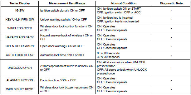
- The wireless door lock control data list can be
displayed while the intelligent tester is connected to
the DLC3 with the ignition switch in the ON position.
Follow the prompts on the tester screen to access the DATA LIST.
BODY:
2. ACTIVE TEST
HINT: Performing the ACTIVE TEST using the intelligent tester allows components such as the relay, VSV and actuator to operate without removing parts. Performing the ACTIVE TEST as the first step in troubleshooting is one way to shorten labor time.
It is possible to display the DATA LIST during the ACTIVE TEST.
- Connect the intelligent tester to the DLC3.
- Turn the ignition switch to the ON position.
- According to the display on the tester, preform the ACTIVE TEST.
HINT: The ignition switch must be turned to the ON position to proceed with the ACTIVE TEST using the intelligent tester.
BODY:

 DTC check / clear
1. DTC CHECK/CLEAR (USING INTELLIGENT TESTER:)
DTC check
Connect the intelligent tester to the DLC3.
Turn the ignition switch to the ON position.
Read the DTCs on t ...
 Diagnostic trouble code chart
HINT:
If a trouble code is displayed during the DTC check,
inspect the circuit listed for that code. For details of the
code, refer to the "See page" in the DTC chart.
...
Other materials:
Engine Coolant Temperature / Intake Air Temperature Correlation
DESCRIPTION
The ECM calculates the difference between the readings of the coolant
temperature sensor and intake air
temperature sensor. If the difference is greater than 20┬░C (68┬░F), the ECM will
judge this as a malfunction
and will set this DTC.
HINT:
Waiting is required t ...
Video terminal
COMPONENTS
REMOVAL
1. REMOVE REAR DOOR SCUFF PLATE LH
2. REMOVE REAR DOOR WEATHERSTRIP LH
3. REMOVE BACK DOOR WEATHERSTRIP
4. REMOVE BACK DOOR SCUFF PLATE
5. REMOVE QUARTER TRIM FRONT PANEL ASSEMBLY LH
6. REMOVE VIDEO(VIDEO ADAPTER) TERMINAL
Release the 4 claw fittings and ...
Moving a second seat for third seat access
Getting in the vehicle
Tip-up seats
Pull the seatback angle adjustment
lever and fold down the
seatback. The cushion will tip
up. The seat can slide forward.
Move the seat to the frontmost
position.
Ottoman seats
Pull the seatback angle adjustment
lever and fold down th ...
