Toyota Sienna Service Manual: Short in Front Passenger Side Squib Circuit
DTC B0105/53 Short in Front Passenger Side Squib Circuit
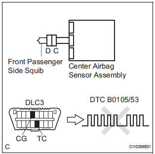
DESCRIPTION
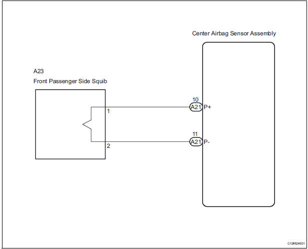
The front passenger side squib circuit consists of the center airbag sensor assembly and the front passenger airbag assembly.
The circuit instructs the SRS to deploy when deployment conditions are met.
DTC B0105/53 is recorded when a short circuit is detected in the front passenger side squib circuit
|
DTC No. |
DTC Detecting Condition |
Trouble Area |
|
B0105/53 |
|
|
WIRING DIAGRAM
INSPECTION PROCEDURE
HINT:
- Perform the simulation method by selecting the "check mode" (signal check) with the intelligent tester
- After selecting the "check mode" (signal check), perform the simulation method by wiggling each connector of the airbag system or driving the vehicle on a city or rough road
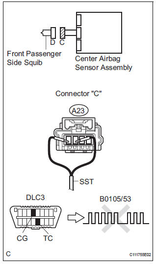
1 CHECK FRONT PASSENGER AIRBAG ASSEMBLY (FRONT PASSENGER SIDE SQUIB)
- Turn the ignition switch to the LOCK position.
- Disconnect the negative (-) terminal cable from the battery, and wait for at least 90 seconds.
- Disconnect the connectors from the front passenger airbag assembly.
- Connect the black wire side of SST (resistance 2.1 Ω) to the instrument panel wire.
CAUTION: Never connect a tester to the front passenger airbag assembly (front passenger side squib) for measurement, as this may lead to a serious injury due to airbag deployment.
NOTICE: Do not forcibly insert the SST into the terminals of the connector when connecting.
Insert the SST straight into the terminals of the connector.
SST 09843-18060
- Connect the negative (-) terminal cable to the battery, and wait for at least 2 seconds.
- Turn the ignition switch to the ON position, and wait for at least 60 seconds.
- Clear the DTCs stored in memory (5).
- Turn the ignition switch to the LOCK position.
- Turn the ignition switch to the ON position, and wait for at least 60 seconds.
- Check the DTCs (5).
OK: DTC B0105/53 is not output. HINT: Codes other than DTC B0105/53 may be output at this time, but they are not related to this check.
 Go to step 2

REPLACE FRONT PASSENGER AIRBAG ASSEMBLY
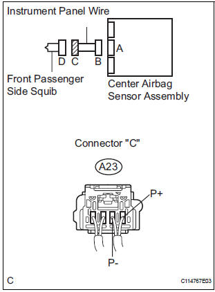
2 CHECK INSTRUMENT PANEL WIRE (FRONT PASSENGER SIDE SQUIB CIRCUIT)
- Turn the ignition switch to the LOCK position.
- Disconnect the negative (-) terminal cable from the battery, and wait for at least 90 seconds.
- Disconnect the SST (resistance 2.1 Ω) from the instrument panel wire.
- Disconnect the connector from the center airbag sensor assembly.
- Release the activation prevention mechanism built into connector "B" (7).
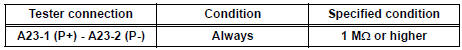
- Measure the resistance according to the value(s) in the table below.
Standard resistance
 REPAIR OR REPLACE INSTRUMENT
PANEL
WIRE
REPAIR OR REPLACE INSTRUMENT
PANEL
WIRE

3 CHECK CENTER AIRBAG SENSOR ASSEMBLY
- Connect the connectors to the front passenger airbag assembly and the center airbag sensor assembly.
- Connect the negative (-) terminal cable to the battery, and wait for at least 2 seconds.
- Turn the ignition switch to the ON position, and wait for at least 60 seconds.
- Clear the DTCs stored in memory (5).
- Turn the ignition switch to the LOCK position.
- Turn the ignition switch to the ON position, and wait for at least 60 seconds.
- Check the DTCs (5).
OK: DTC B0105/53 is not output. HINT: Codes other than code B0105/53 may be output at this time, but they are not related to this check.
 REPLACE CENTER AIRBAG SENSOR
ASSEMBLY
REPLACE CENTER AIRBAG SENSOR
ASSEMBLY

USE SIMULATION METHOD TO CHECK
 Short to B+ in Driver Side Squib Circuit
DTC B0103/12 Short to B+ in Driver Side Squib Circuit
DESCRIPTION
The driver side squib circuit consists of the center airbag sensor assembly,
the spiral cable and the
steering pad.
The circui ...
 Open in Front Passenger Side Squib Circuit
DTC B0106/54 Open in Front Passenger Side Squib Circuit
DESCRIPTION
The front passenger side squib circuit consists of the center airbag sensor
assembly and the front
passenger airbag assembly.
...
Other materials:
Open in Rear Curtain Shield Squib RH Circuit
DTC B1631/84 Open in Rear Curtain Shield Squib RH Circuit
DESCRIPTION
The rear curtain shield squib RH circuit consists of the center airbag sensor
assembly and the curtain
shield airbag assembly RH.
The circuit instructs the SRS to deploy when deployment conditions are met.
DTC B1631/84 ...
Short in Front Passenger Side Squib 2nd Step
Circuit
DTC B1185/57 Short in Front Passenger Side Squib 2nd Step
Circuit
DESCRIPTION
The front passenger side squib 2nd step circuit consists of the center airbag
sensor assembly and the
front passenger airbag assembly.
The circuit instructs the SRS to deploy when deployment conditions are met.
...
Gauges and meters
The displayed content may differ depending on the type of meter.
Vehicles with monochrome display
Vehicles with color display
Tachometer
Displays the engine speed in revolutions per minute
Multi-information display
Presents the driver with a variety of driving-related d ...
