Toyota Sienna Service Manual: Description of code registration
It is necessary to register the transmitter ID in the tire pressure warning ECU when replacing the tire pressure warning valve and transmitter and/or tire pressure warning ECU.
(a) Before registration
(1) In case of tire pressure warning ECU replacement.
- Read the registered transmitter IDs that are stored in the old ECU using the intelligent tester and note them down.
- If reading stored transmitter IDs is impossible due to malfunctions of components such as the tire pressure warning antenna and receiver, remove the tires from the wheels and check the IDs located on the tire pressure warning valves and transmitters (See page TW-10).
(2) In case of tire pressure warning valve and transmitter replacement.
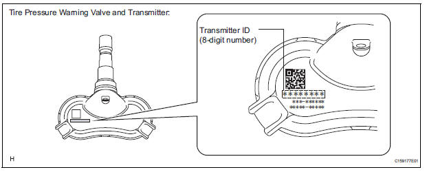
- When replacing the tire pressure warning valves and transmitters, note down the IDs written on the tire pressure warning valves and transmitters.
- Take a note of the 8-digit number (transmitter ID) written on the tire pressure warning valve and transmitter.
NOTICE:
- The transmitter ID is written on the tire pressure warning valve and transmitter. It will be unable to be read after installing the tire pressure warning valve and transmitter on the tire and wheel. Therefore, take a note of the transmitter ID before installing the tire pressure warning valve and transmitter.
- The ID registration must be performed for all tire pressure warning valve and transmitters. Check the DATA LIST, replace the exchanged ID with a new ID, and make a new data list of all 4 tires for the vehicle.
 Registration
...
 Register transmitter id (using intelligent tester)
(a) Connect the intelligent tester to DLC3 (Procedure
"A").
(b) Turn the ignition switch to the ON position
(Procedure "B").
(c) Select the REGIST TIRE following the intell ...
Other materials:
Power Slide Door does not Fully Open
DESCRIPTION
When the LH / RH rear window is open 105 mm (5.91 in.) or more,
the slide door half-open stopper is
activated to force the slide door to stop at approximately 105 mm (5.91 in.)
from the fully open position.
This is caused by the jam protection function between the sli ...
Installation
1. INSTALL TRANSFER EXTENSION HOUSING TYPE T OIL SEAL
(a) Using SST(s), install anew transfer extension
housing type T oil seal to he transfer extension
housing sub-assembly at the position show in the
illustration.
SST 09325-20010
NOTICE:
Do not install the oil seal obliquely.
(b) Apply ...
High Temperature
DTC 44-47 High Temperature
DESCRIPTION
DTC No.
DTC Detection Condition
Trouble Area
44-47
Sensor detects that DVD unit temperature is high (Over
80C).
Television display assembly
INSPECTION PROCEDURE
HINT:
After the inspection is completed, cl ...
