Toyota Sienna Service Manual: Folding Motor Circuit
DESCRIPTION
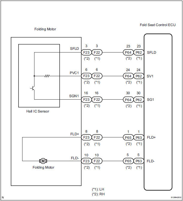
The fold seat control ECU receives a switch operation signal from the fold seat switch and activates the folding motor. At this time, the Hall IC (seat cushion position sensor) detects the actuation signal. The fold seat control ECU uses signals from the Hall IC (seat cushion position sensor) to detect if an object if an object is caught or if any other abnormal condition has occurred.
WIRING DIAGRAM
INSPECTION PROCEDURE
1 INSPECT FOLD SEAT CONTROL ECU
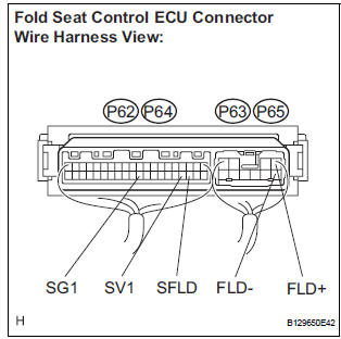
- Remove the fold seat control ECU.
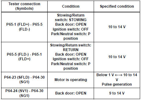
- Measure the voltage according to the value(s) in the table below.
Standard voltage: LH side
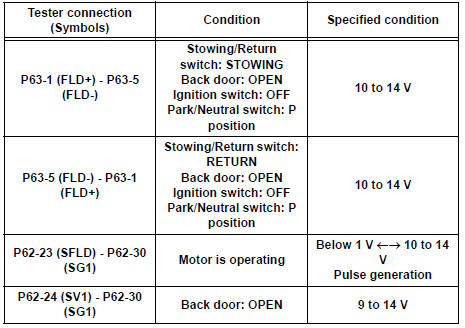
RH side
2 CHECK HARNESS AND CONNECTOR (FOLD SEAT CONTROL ECU - FOLDING MOTOR)
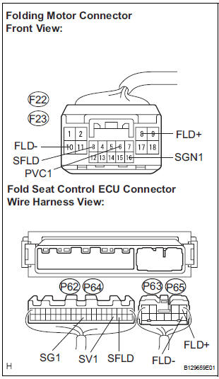
- Disconnect the connector from the fold seat control ECU.
- Disconnect the connector from the fold seat motor.
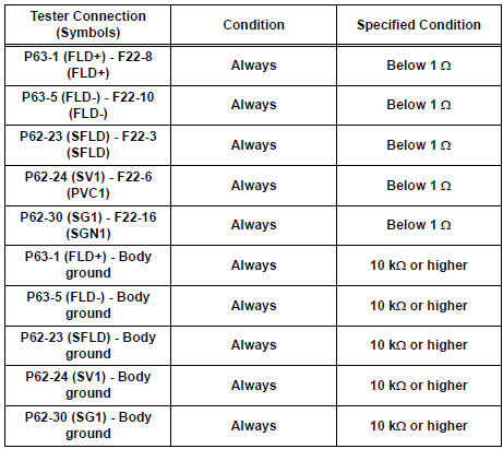
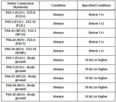
- Measure the resistance according to the value(s) in the table below.
Standard resistance: LH side
RH side
PROCEED TO NEXT CIRCUIT INSPECTION SHOWN IN PROBLEM SYMPTOMS TABLE
 Fold Seat Switch Circuit
DESCRIPTION
When the fold seat switch is operated, a switch operation signal is sent to
the fold seat control ECU. The
ECU receives switch operation signals from each switch and activates the fold ...
 Reclining Motor Circuit
DESCRIPTION
The fold seat control ECU receives a switch operation signal from the power
rear no. 2 seat switch and
the fold seat switch, and activates the reclining motor. At this time, the Hall
...
Other materials:
Television Display Power Source Circuit
DESCRIPTION
This is the power source circuit to operate the television display assembly.
WIRING DIAGRAM
INSPECTION PROCEDURE
1 INSPECT TELEVISION DISPLAY ASSEMBLY
Disconnect the connector from the television display
assembly.
Measure the resistance according to the value(s) ...
Disassembly
1. REMOVE FRONT SEAT SIDE TABLE LEG COVER (w/
Table)
Using a screwdriver, disengage the claws and
remove the seat side table leg cover.
HINT:
Tape the screwdriver tip before use.
2. REMOVE FRONT SEAT SIDE TABLE (w/ Table)
Remove the 4 nuts and seat side table.
Rem ...
Front Clearance Sonar Sensor LH Circuit
DESCRIPTION
An ultrasonic sensor consists of a sensor portion that transmits and receives
ultrasonic waves and a preamplifier
that amplifies them. The ultrasonic sensor outputs the ultrasonic waves and
sends the received
signals to the clearance warning ECU.
WIRING DIAGRAM
INSPECTION PROC ...
