Toyota Sienna Service Manual: Diagnosis system
1. CHECK DLC3
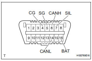
- The vehicle's ECU uses ISO 15765-4 for communication protocol. The terminal arrangement of the DLC3 complies with SAE J1962 and matches the ISO 15765-4 format.

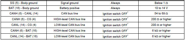
NOTICE: *: Before measuring the resistance, leave the vehicle as is for at least 1 minute and do not operate the ignition switch, any other switches or the doors.
If the result is not as specified, the DLC3 may have a malfunction. Repair or replace the harness and connector.
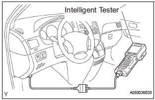
- Connect the cable of the intelligent tester to the DLC3, turn the ignition switch to the ON position and attempt to use the intelligent tester. If the screen displays a communication error message, a problem exists in the vehicle side of the tester side.
HINT:
- If communication is normal when the tool is connected to another vehicle, inspect the DLC3 on the original vehicle.
- If communication is still impossible when the tool is connected to another vehicle, the problem is probably in the tool itself. Consult the Service Department listed in the tool's instruction manual.
 Problem symptoms table
POWER WINDOW CONTROL SYSTEM (W/ JAM PROTECTION)
Symptom
Suspected Area
AUTO UP/DOWN function does not operate
Power window regulator motor assembly (Driver side ...
 Data list / active test
1. USING INTELLIGENT TESTER
Connect the intelligent tester to the DLC3.
Monitor the ECU data by following the prompts on
the tester screen.
HINT:
The intelligent tester has a & ...
Other materials:
Fuel pump resistor
Components
REMOVAL
1. REMOVE FUEL PUMP RESISTOR
(a) Disconnect the connector.
(b) Remove the nut and fuel pump resistor.
INSPECTION
1. INSPECT FUEL PUMP RESISTOR
(a) Inspect fuel pump resistor.
(1) Using an ohmmeter, measure the resistance
between the terminals.
Standard resi ...
Fastening the seat belt (for the third center seat)
Take the plate out of the holder,
and then pull down the seat
belt.
Push plate “A” into buckle “A”
until a click sound is heard.
Push plate “B” into buckle “B”
until a click sound is heard.
...
Suspension system
How to proceed with troubleshooting
HINT:
This is the repair procedure for vehicle pull.
Problem symptoms table
FRONT SUSPENSION SYSTEM
REAR SUSPENSION SYSTEM
...
