Toyota Sienna Service Manual: Diagnosis system
1. CHECK DLC3
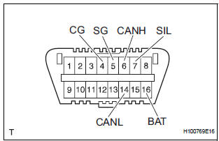
- The vehicle's ECU uses ISO 15765-4 for communication protocol. The terminal arrangement of the DLC3 complies with SAE J1962 and matches the ISO 15765-4 format.
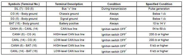
NOTICE: *: Before measuring the resistance, leave the vehicle as is for at least 1 minute and do not operate the ignition switch, any other switches or the doors.
If the result is not as specified, the DLC3 may have a malfunction. Repair or replace the harness and connector.
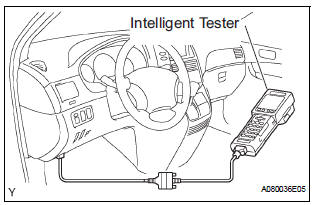
- Connect the cable of the intelligent tester to the DLC3, turn the ignition switch to the ON position and attempt to use the intelligent tester. If the screen displays a communication error message, a problem exists in the vehicle side of the tester side.
HINT:
- If communication is normal when the tool is connected to another vehicle, inspect the DLC3 on the original vehicle.
- If communication is still impossible when the tool is connected to another vehicle, the problem is probably in the tool itself. Consult the Service Department listed in the tool's instruction manual.
2. BACK DOOR LOCK
- When the battery is reconnected: The back door is locked and therefore cannot be opened. Therefore, it is necessary to unlock the back door using the door control switch or transmitter switch.
 Terminals of ECU
1. CHECK POWER BACK DOOR ECU
Disconnect the P13 and P14 ECU connectors, and
check the voltage and resistance of each terminal of
the wire harness side connectors
If the result is no ...
 DTC check / clear
1. CHECK DTC (USING INTELLIGENT TESTER)
Checking DTCs.
Connect the intelligent tester to the DLC3.
Turn the ignition switch ON.
Read DTCs by following the pro ...
Other materials:
Reverse Signal Circuit
DESCRIPTION
The radio and navigation assembly receives a reverse signal from the
park/neutral position switch and
information about the GPS antenna, and then adjusts vehicle position.
WIRING DIAGRAM
INSPECTION PROCEDURE
1 INSPECT RADIO AND NAVIGATION ASSEMBLY
Disconnect the radio ...
Disassembly
1. REMOVE FRONT SEAT SIDE TABLE LEG COVER (w/
Table)
Using a screwdriver, disengage the claws and
remove the seat side table leg cover.
HINT:
Tape the screwdriver tip before use.
2. REMOVE FRONT SEAT SIDE TABLE (w/ Table)
Remove the 4 nuts and seat side table.
Rem ...
On-vehicle inspection
1. INSPECT REAR AXLE HUB BEARING BACKLASH
(a) Using a dial gauge, check for backlash near the
center of the axle hub.
Maximum:
0.05 mm (0.0020 in.)
If backlash exceeds the maximum, replace the axle
hub assembly.
NOTICE:
Ensure that the dial gauge is set at right angles
to the measuremen ...
