Toyota Sienna Service Manual: Diagnosis system
1. CHECK DLC3

- The vehicle's ECU uses ISO 15765-4 for communication protocol. The terminal arrangement of the DLC3 complies with SAE J1962 and matches the ISO 15765-4 format.
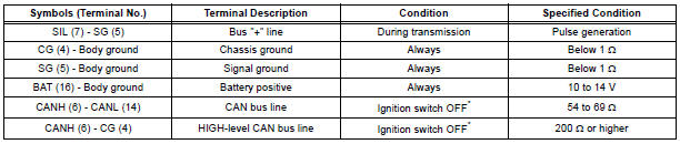
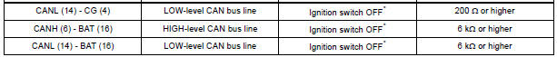
NOTICE: *: Before measuring the resistance, leave the vehicle as is for at least 1 minute and do not operate the ignition switch, any other switches or the doors.
If the result is not as specified, the DLC3 may have a malfunction. Repair or replace the harness and connector.
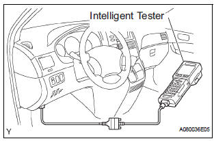
- Connect the cable of the intelligent tester to the DLC3, turn the ignition switch to the ON position and attempt to use the intelligent tester. If the screen displays a communication error message, a problem exists in the vehicle side of the tester side.
HINT:
- If communication is normal when the tool is connected to another vehicle, inspect the DLC3 on the original vehicle.
- If communication is still impossible when the tool is connected to another vehicle, the problem is probably in the tool itself. Consult the Service Department listed in the tool's instruction manual.
2. BACK DOOR LOCK
- When the battery is reconnected: The back door is locked and therefore cannot be opened. Therefore, it is necessary to unlock the back door using the door control switch or transmitter switch.
 Terminals of ECU
1. CHECK POWER BACK DOOR ECU
Disconnect the P13 and P14 ECU connectors, and
check the voltage or resistance of each terminal of
the wire harness side connectors
If the result is not ...
 DTC check / clear
1. CHECK DTC (USING INTELLIGENT TESTER)
Checking DTCs.
Connect the intelligent tester to the DLC3.
Turn the ignition switch ON.
Read DTCs by following the prompts on the
tester scr ...
Other materials:
2Gr-fe engine mechanical
SERVICE DATA
TORQUE SPECIFICATIONS
2GR-FE FUEL
SERVICE DATA
TORQUE SPECIFICATIONS
2GR-FE EMISSION CONTROL
SERVICE DATA
TORQUE SPECIFICATIONS
2GR-FE INTAKE
SERVICE DATA
TORQUE SPECIFICATIONS
2GR-FE EXHAUST
SERVICE DATA
TORQUE SPECIFICAT ...
Problem symptoms table
HINT:
Inspect the fuse and relay before confirming the suspected
areas in the table below.
Inspect each suspected area in numerical order for the
corresponding symptom.
If the malfunction still exists after checking and confirming
that all circuits and components are normal ...
Disassembly
1. REMOVE PARKING BRAKE PEDAL BRACKET PROTECTOR
(a) Using a flat-head screwdriver, disengage the 2
claws on the parking brake pedal bracket protector.
(b) Turning the parking brake pedal bracket protector
clockwise, remove the parking brake pedal bracket
protector from the parking brake ...
