Toyota Sienna Service Manual: Disassembly
1. REMOVE PARKING BRAKE PEDAL BRACKET PROTECTOR
(a) Using a flat-head screwdriver, disengage the 2 claws on the parking brake pedal bracket protector.
(b) Turning the parking brake pedal bracket protector clockwise, remove the parking brake pedal bracket protector from the parking brake control pedal.
2. REMOVE PARKING BRAKE CABLE ASSEMBLY NO.1
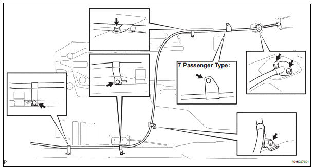
(a) Remove the lock nut, adjusting nut, clip and disconnect the parking brake cable assembly No. 1 from the parking brake control pedal assembly.
(b) Take up the floor carpet.
(c) Remove the 6 bolts and disconnect the parking brake cable assembly No. 1 from the floor. (Except 7 Passenger Type) (d) Remove the 7 bolts and disconnect the parking brake cable assembly No. 1 from the floor. (7 Passenger Type) (e) Disconnect the parking brake cable No. 1 from the parking brake equalizer, and remove the parking brake cable No. 1.
3. REMOVE PARKING BRAKE SWITCH ASSEMBLY
(a) Remove the screw and parking brake switch.
 Removal
1. DISCONNECT BATTERY NEGATIVE TERMINAL
2. REMOVE FRONT DOOR SCUFF PLATE LH
3. REMOVE COWL SIDE TRIM BOARD LH
4. REMOVE INSTRUMENT PANEL FINISH PANEL SUBASSEMBLY
LOWER LH (See page IP-6)
5. REMOV ...
 Reassembly
1. INSTALL PARKING BRAKE SWITCH ASSEMBLY
(a) Install the parking brake switch to the parking brake
pedal with the screw.
2. INSTALL PARKING BRAKE CABLE ASSEMBLY NO.1
(a) Connect the parking brake ...
Other materials:
Speed sensor check (when using sst check wire)
(a) Check the speed sensor signal.
(1) Drive the vehicle straight forward. Drive the
vehicle at a speed of 45 km/h (28 mph) or higher
for several seconds and check that the ABS
warning light goes off.
HINT:
The signal check may not be completed if the
vehicle has its wheels spun or the stee ...
Removal
1. RECOVER REFRIGERANT FROM REFRIGERATION
SYSTEM (See page AC-172)
2. REMOVE FRONT WHEEL RH
3. REMOVE FRONT FENDER APRON SEAL RH (See
page EM-26)
4. REMOVE V-RIBBED BELT (See page EM-6)
5. REMOVE RADIATOR AND FAN ASSEMBLY
(See page CO-28)
6. DISCONNECT DISCHARGE HOSE SUB-ASSEMBLY
(a) Re ...
Precaution
1. INSPECTION PROCEDURE FOR VEHICLE INVOLVED
IN ACCIDENT
Perform the zero point calibration and sensitivity
check if any of the following conditions occur.
The occupant classification ECU is replaced.
Accessories (seatback tray and seat cover, etc.)
are installed.
...
