Toyota Sienna Service Manual: Disassembly
HINT: Overhaul the RH side by the same procedures as these of the LH side.
1. REMOVE REAR WHEEL
2. SEPARATE REAR DISC BRAKE CALIPER ASSEMBLY LH
HINT: Do not disconnect the flexible hose from the brake caliper.
3. REMOVE REAR DISC
(a) Release the parking brake, and remove the rear disc.
HINT:
- Align matchmarks on the disc and the axle hub.
- If the disc cannot be removed easily, turn the shoe adjuster until the wheel turns freely.
4. REMOVE PARKING BRAKE SHOE ASSEMBLY LH NO.1
(a) Using needle-nose pliers, remove the 2 shoe return tension springs.
(b) Disconnect the tension spring from the parking brake shoe assembly LH No. 1.
(c) Slide out the parking brake shoe assembly LH No. 1 and remove the parking brake shoe assembly LH No. 1.
(d) Remove the shoe hold-down compression spring, 2 cups and shoe hold-down compression spring pin No. 1.
5. REMOVE PARKING BRAKE SHOE ADJUSTING SCREW SET
6. REMOVE PARKING BRAKE SHOE STRUT LH
7. REMOVE PARKING BRAKE SHOE ASSEMBLY LH NO.2
(a) Disconnect the return spring from the parking brake shoe assembly LH No. 2 and remove the tension spring.
(b) Slide out the parking brake shoe assembly LH No.
2.
(c) Remove the shoe hold-down compression spring, 2 cups and shoe hold-down compression spring pin No. 2.
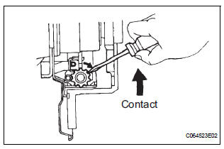
(d) Using needle-nose pliers, disconnect the parking brake cable No. 3 from the parking brake shoe lever and remove the parking brake shoe assembly LH No. 2.
8. REMOVE PARKING BRAKE SHOE LEVER LH
(a) Using a screwdriver, remove the C-washer.
(b) Remove the shim and shoe lever from the parking brake shoe.
 Parking brake assembly
COMPONENTS
...
 Inspection
1. INSPECT BRAKE DISC INSIDE DIAMETER
(a) Using a brake drum gauge or equivalent, measure
the inside diameter of the disc.
Standard inside diameter:
190 mm (7.480 in.)
Maximum inside diameter ...
Other materials:
Internal Control Module Random Access Memory
(RAM) Error
DTC P0604 Internal Control Module Random Access Memory
(RAM) Error
DESCRIPTION
The ECM continuously monitors its own internal memory status, internal
circuits, and output signals
transmitted to the throttle actuator. This self-check ensures that the ECM is
functioning properly. If any
malfu ...
Short to B+ in Curtain Shield Squib RH Circuit
DTC B1163/82 Short to B+ in Curtain Shield Squib RH Circuit
DESCRIPTION
The curtain shield squib RH circuit consists of the center airbag sensor
assembly and the curtain shield
airbag assembly RH.
The circuit instructs the SRS to deploy when deployment conditions are met.
DTC B1163/82 is ...
On-vehicle inspection
1. INSPECT STEERING PAD (VEHICLE NOT INVOLVED IN COLLISION)
Perform a diagnostic system check.
With the steering pad installed on the vehicle,
perform a visual check. If there are any defects as
mentioned below, replace the steering pad with a
new one:
Cuts, minute cracks or marked ...
