Toyota Sienna Service Manual: Precaution
1. Before operating the power rear no. 2 seat with stowing function, make sure that there is nothing in the path of the seat.
CAUTION: If someone or something is caught between the seat and other parts, injury or damage may result.
- If the system detects that the folding motor is locked due to an object that is caught between the seat cushion and floor, a warning buzzer will sound for 10 seconds and the indicator on the fold seat switch will blink.
2. Before operating the power rear no. 2 seat with stowing function, make sure that there is nothing on the seat.
HINT: If the system detects that an object is caught in the seat when the folding switch is operated, operating the stowing switch right after the detection will not cause the seat to move.
- If the system detects that an object is caught between the seat cushion and seatback, a warning buzzer will sound for 10 seconds and the indicator on the fold seat switch will blink.
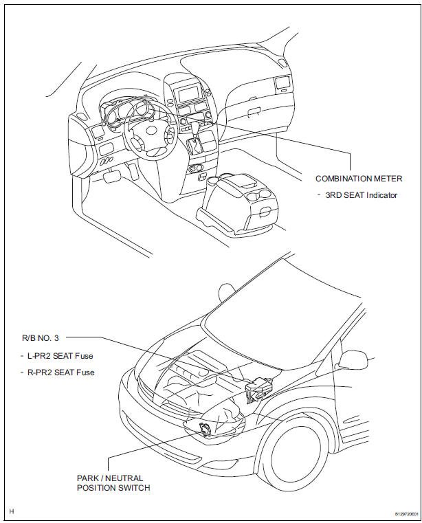
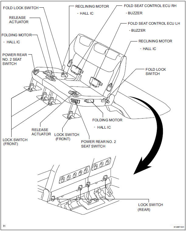
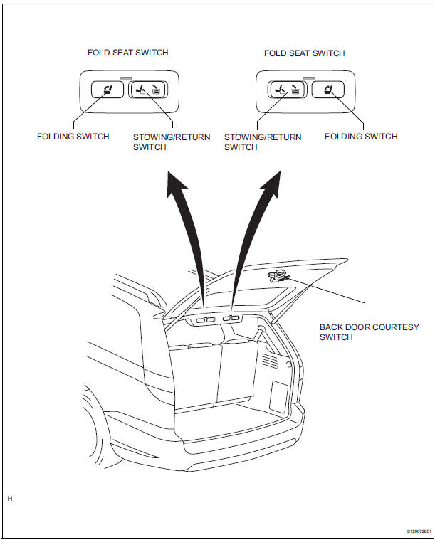
PARTS LOCATION
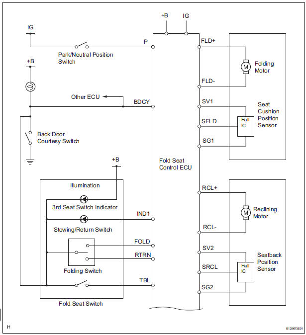
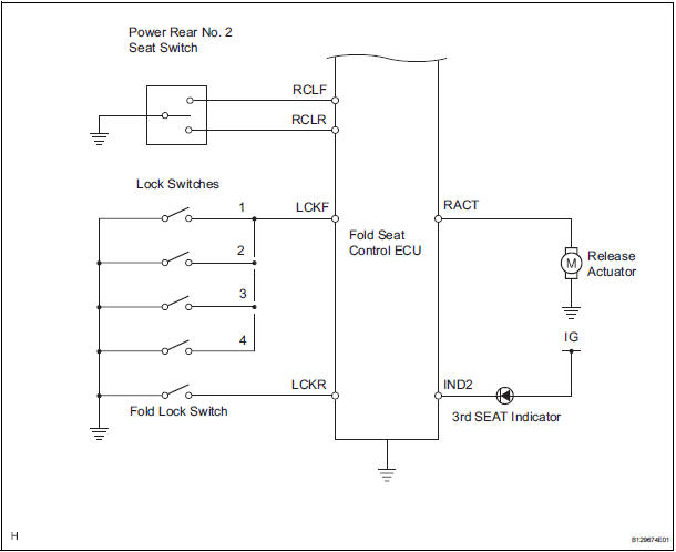
SYSTEM DIAGRAM

 System description
1. DESCRIPTION OF POWER REAR NO. 2 SEAT WITH
STOWING FUNCTION
A power rear no. 2 seat with stowing function has
been adopted for the third-row seats.
The power rear no. 2 seat wit ...
Other materials:
ECM Power Source Circuit
DESCRIPTION
When the ignition switch is turned to the ON position, the battery voltage is
applied to terminal IGSW of
the ECM. The ECM MREL output signal causes a current to flow to the coil,
closing the contacts of the EFI
relay and supplying power to terminal +B of the ECM.
If the igniti ...
Problem symptoms table
HINT:
Before inspecting the suspected areas listed in the table
below, check the fuse and relay.
Before inspecting the suspected areas listed in the table
below, check for DTCs.
Methods used to verify the cause of the problem are listed
in order of probability in the ...
Headlight dimmer switch
COMPONENTS
REMOVAL
1. REMOVE STEERING COLUMN LOWER COVER
2. REMOVE STEERING COLUMN UPPER COVER
3. REMOVE HEADLIGHT DIMMER SWITCH ASSEMBLY
Disconnect the connector.
Release the claw fitting and remove the headlight
dimmer switch assembly.
INSPECTION
1. HEADLIGHT DI ...
