Toyota Sienna Service Manual: Compressor Lock Sensor Circuit
DTC B1422/22 Compressor Lock Sensor Circuit
SYSTEM DESCRIPTION
The ECM sends an engine speed signal to the A/C amplifier via CAN communication and BEAN communication.
The A/C amplifier reads the difference between compressor speed and engine
speed. When the
difference becomes too large, the A/C amplifier determines that the compressor
locks, and turns the
magnetic clutch off.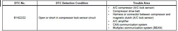
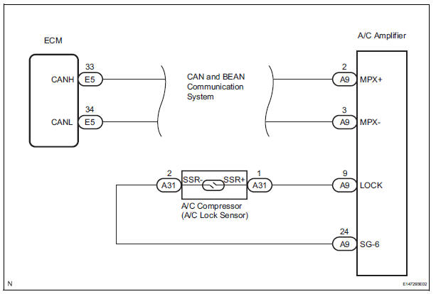
WIRING DIAGRAM
INSPECTION PROCEDURE
1 CHECK CAN COMMUNICATION SYSTEM
(a) Use the intelligent tester to check if the CAN communication system is functioning normally.
Result 


2 CHECK MULTIPLEX COMMUNICATION SYSTEM
(a) Use the intelligent tester to check if the multiplex communication system (BEAN) is functioning normally.
Result 

3 INSPECT A/C AMPLIFIER
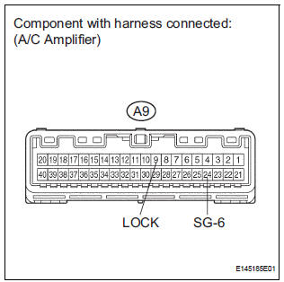
(a) Remove the A/C amplifier with the connectors still connected.
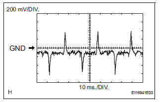
(b) Measure the waveform of the connector.
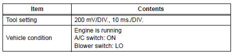
Standard 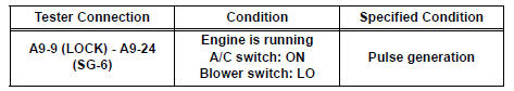
Result 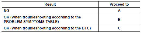

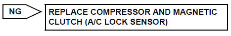
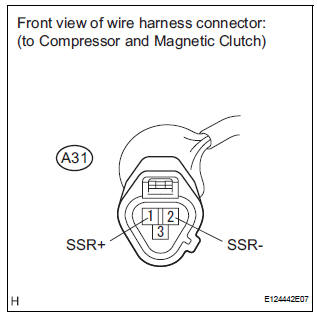
4 INSPECT COMPRESSOR AND MAGNETIC CLUTCH (A/C LOCK SENSOR)
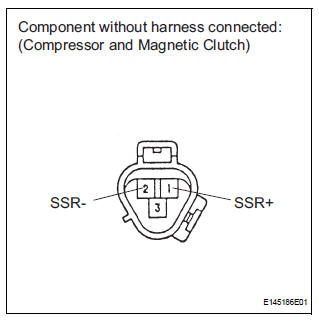
(a) Disconnect the connector from the A/C compressor.
(b) Measure the resistance according to the value(s) in the table below.
Standard resistance 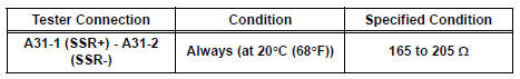

5 CHECK HARNESS AND CONNECTOR (A/C AMPLIFIER - A/C LOCK SENSOR)

(a) Disconnect the connector from the A/C amplifier.
(b) Measure the resistance according to the value(s) in the table below.
Standard resistance 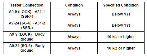

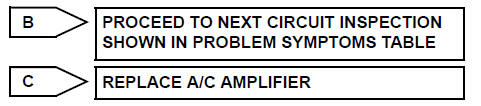
REPLACE A/C AMPLIFIER
 Solar Sensor Circuit (Passenger Side)
DTC B1421/21 Solar Sensor Circuit (Passenger Side)
DESCRIPTION
The solar sensor, which is installed on the upper side of the instrument
panel, detects sunlight and
controls the air conditioni ...
 Pressure Sensor Circuit
DTC B1423/23 Pressure Sensor Circuit
DESCRIPTION
This DTC is output when refrigerant pressure on the high pressure side is
extremely low (0.19 MPa (2.0
kgf/cm2, 28 psi) or less) or extremely high ...
Other materials:
Installation
1. INSTALL ECM
Install the ECM with the 2 nuts.
Torque: 5.5 N*m (56 kgf*cm, 49 in.*lbf)
Connect the 5 ECM connectors.
2. INSTALL ECM (with 10 speakers system)
Install the ECM and stereo components amplifier
with the 4 nuts.
Torque: 5.5 N*m (56 kgf*cm, 49 ...
On-vehicle inspection
1. CHECK ACCELERATOR PEDAL ROD
Check the voltage.
Connect the intelligent tester to the DLC3.
Turn the ignition switch to the ON position.
Turn the intelligent tester on.
Select the menu items: DIAGNOSIS /
ENHANCED OBD II / DATA LIST / ALL /
ACCEL POS ...
Data list / active test
1. USING INTELLIGENT TESTER
Connect the intelligent tester to the DLC3.
Monitor the ECU data by following the prompts on
the tester screen.
HINT:
The intelligent tester has a "Snapshot" function
which records the monitored data.
Refer to the intelligent tester o ...
