
Toyota Sienna Service Manual: Disassembly
1. REMOVE OCCUPANT CLASSIFICATION ECU
2. REMOVE FRONT SEAT CUSHION SHIELD INNER RH
- Remove the screw.
- Using a screwdriver, disengage the claws and remove the cushion shield inner.
HINT: Tape the screwdriver tip before use.
3. REMOVE FRONT SEAT INNER BELT ASSEMBLY RH
- Disconnect the connectors.
- Remove the nut and inner belt assembly.
4. REMOVE RECLINING ADJUSTER RELEASE HANDLE RH
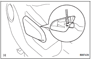
- Using a screwdriver, disengage the claws and remove the reclining adjuster release handle.
HINT: Tape the screwdriver tip before use.
5. REMOVE FRONT SEAT CUSHION SHIELD RH
- Remove the screw.
- Using a screwdriver disengage the claws and remove the cushion shield.
HINT: Tape the screwdriver tip before use.
6. REMOVE FRONT SEAT TRACK COVER RH FRONT INNER
- Remove the clip, 2 screws and seat track cover front inner.
7. REMOVE FRONT SEAT TRACK COVER RH FRONT OUTER
- Remove the clip, 2 screws and seat track cover front outer.
8. REMOVE FRONT SEAT INNER RH ARMREST ASSEMBLY
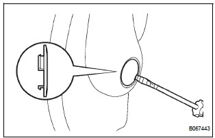
- Using a screwdriver, remove the armrest cap.
HINT: Tape the screwdriver tip before use.
- Remove the bolt and armrest assembly.
- ) Remove the 2 washers and 2 spacers.
9. REMOVE FRONT SEATBACK SHIELD LH
- Using a screwdriver, disengage the claws and
remove the reclining adjuster release handle.
HINT: Tape the screwdriver tip before use.
- Remove the screw and seatback shield.
10. REMOVE FRONT SEATBACK SHIELD RH
HINT: Use the same procedures for the RH side and LH side.
11. REMOVE FRONT SEATBACK BOARD RH
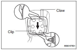
- Disengage the clips.
- Remove the seatback board by pulling it out in the arrow mark direction shown in the illustration.
12. REMOVE FRONT SEATBACK SPRING ASSEMBLY
- Remove the 4 bolts and seatback spring assembly together with the seatback cover.
13. REMOVE FRONT SEATBACK LOCK SUB-ASSEMBLY LH
- Remove the 2 bolts and seatback lock assembly.
14. REMOVE FRONT SEATBACK LOCK SUB-ASSEMBLY RH
- Remove the reclining connecting pipe.
- Remove the 2 bolts and seatback lock assembly.
15. REMOVE FRONT SEAT HINGE COVER LH
- Using a screwdriver, disengage the claws and remove the seat hinge cover.
HINT: Tape the screwdriver tip before use.
16. REMOVE FRONT SEAT HINGE COVER RH
HINT: Use the same procedures for the RH side and LH side.
17. REMOVE FRONT SEAT HEADREST SUPPORT
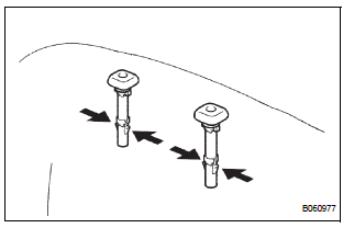
- Disengage the claws and remove the 2 headrest supports.
18. REMOVE FRONT SEATBACK COVER RH
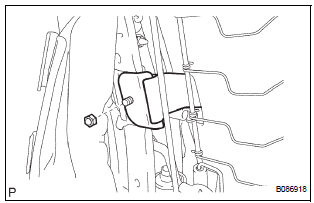
- with Side airbag: Remove the nut and disengage the separate type front seatback cover bracket.
- Remove the hog rings and seatback cover together with the pad.
- Remove the hog rings and seatback cover.
19. REMOVE SEPARATE TYPE FRONT SEAT CUSHION COVER
- Disengage the hook and remove the seat cushion cover together with the pad.
- Remove the hog rings and seat cushion cover.
20. REMOVE RECLINING ADJUSTER INSIDE COVER LH
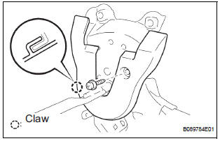
- Remove the screw and the reclining adjuster inside cover LH (lower).
21. REMOVE RECLINING ADJUSTER INSIDE COVER RH
HINT: Use the same procedures for the RH side and LH side.
22. REMOVE RECLINING ADJUSTER INSIDE COVER LH
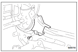
- Remove the screw and the reclining adjuster inside cover LH (upper).
23. REMOVE RECLINING ADJUSTER INSIDE COVER RH
HINT: Use the same procedures for the RH side and LH side.
24. REMOVE FRONT SEAT CUSHION SHIELD LOWER LH
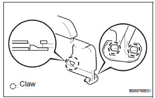
- Using a screwdriver, disengage the claws and remove the front seat cushion shield lower LH.
HINT: Tape the screwdriver tip before use.
25. REMOVE FRONT SEAT CUSHION SHIELD LOWER RH
HINT: Use the same procedures for the RH side and LH side.
 Removal
CAUTION:
Wear safety gloves, because the sharp surfaces of the
seatback frame and seat adjuster may injure your
hand.
Work must be started more than 90 seconds after the
igniti ...
 Reassembly
1. INSTALL FRONT SEAT CUSHION SHIELD LOWER LH
Install the front seat cushion shield lower LH.
2. INSTALL FRONT SEAT CUSHION SHIELD LOWER
RH
3. INSTALL RECLINING ADJUSTER INSIDE COVER LH ...
Other materials:
Adjustment
1. VEHICLE PREPARATION FOR FOG LIGHT AIMING
Prepare the vehicle:
Ensure there is no damage or deformation to the
body around the fog lights.
Fill the fuel tank.
Make sure that the oil is filled to the specified
level.
Make sure that the coolant is fi ...
DSP Error
DTC 44-78 DSP Error
DESCRIPTION
DTC No.
DTC Detection Condition
Trouble Area
44-78
An error occurs during the decode process (MP3 /
WMA).
-
INSPECTION PROCEDURE
HINT:
After the inspection is completed, clear the DTCs.
NOTICE:
Th ...
Cold Start Ignition Timing Performance
DESCRIPTION
This monitor will run when the engine is started at -10 to 50°C (14 to 122°F)
of the engine coolant
temperature. The DTC will set after the engine idling for 13 seconds (2 trip
detection logic).
The DTC is designed to monitor the idle air control at cold start. When the
...
