Toyota Sienna Service Manual: Reassembly
1. INSTALL FRONT SEAT CUSHION SHIELD LOWER LH
- Install the front seat cushion shield lower LH.
2. INSTALL FRONT SEAT CUSHION SHIELD LOWER RH
3. INSTALL RECLINING ADJUSTER INSIDE COVER LH
- Install the reclining adjuster inside cover LH (upper) with the screw.
4. INSTALL RECLINING ADJUSTER INSIDE COVER RH
HINT: Use the same procedures for the RH side and LH side.
5. INSTALL RECLINING ADJUSTER INSIDE COVER LH
- Install the reclining adjuster inside cover LH (lower) with the screw.
6. INSTALL RECLINING ADJUSTER INSIDE COVER RH
HINT: Use the same procedures for the RH side and LH side.
7. INSTALL SEPARATE TYPE FRONT SEAT CUSHION COVER
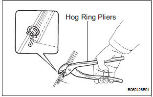
- Install the seat cushion pad to the seat cushion cover.
- Using hog ring pliers, install the seat cushion cover to the seat cushion pad with new hog rings.
NOTICE:
- Be careful not to damage the cover.
- When installing the hog rings, take care to prevent wrinkles as much as possible.
8. INSTALL FRONT SEATBACK COVER RH
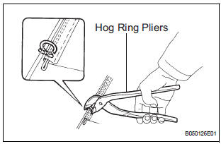
- Install the seatback pad.
- Cover the top of the seatback pad with the seatback cover.
- Using hog ring pliers, completely install the seatback cover with new hog rings.
NOTICE:
- Be careful not to damage the cover.
- When installing the hog rings, take care to prevent wrinkles as much as possible.
- with Side airbag:
Install the seatback cover bracket with the nut.
Torque: 5.5 N*m (56 kgf*cm, 48 in.*lbf)
NOTICE:
- For a vehicle with side airbag, the side airbag may not be activated normally unless the seatback cover is securely installed.
- Check that the strap has no twist after installing the bracket.
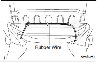
- Attach a rubber wire with new hog rings, as shown in the illustration.
- Using hog ring pliers, install new hog rings.
NOTICE:
- Be careful not to damage the cover.
- When installing the hog rings, take care to prevent wrinkles as much as possible.
9. INSTALL FRONT SEAT HEADREST SUPPORT
- Install the 2 headrest supports.
10. INSTALL FRONT SEAT HINGE COVER LH
- Install the seat hinge cover.
11. INSTALL FRONT SEAT HINGE COVER RH
- Install the seat hinge cover.
12. INSTALL FRONT SEATBACK LOCK SUB-ASSEMBLY RH
- Install the seatback lock assembly with 2 bolts.
Torque: 43 N*m (439 kgf*cm, 32 ft.*lbf)
13. INSTALL FRONT SEATBACK LOCK SUB-ASSEMBLY LH
- Install the seatback lock assembly with 2 bolts.
Torque: 43 N*m (439 kgf*cm, 32 ft.*lbf)
14. INSTALL FRONT SEATBACK SPRING ASSEMBLY
- Install the seatback spring assembly with 4 bolts.
Torque: 43 N*m (439 kgf*cm, 32 ft.*lbf)
15. INSTALL FRONT SEATBACK BOARD RH
- Install front seatback board RH.
- Install the clips.
16. INSTALL FRONT SEAT BACK SHIELD LH
- Install the seatback shield.
- Install the reclining adjuster release handle.
17. INSTALL FRONT SEAT INNER RH ARMREST ASSEMBLY
- Install the armrest assembly with the bolt.
Torque: 20 N*m (200 kgf*cm, 14 ft.*lbf)
- Install the armrest cap.
18. INSTALL FRONT SEAT TRACK COVER RH FRONT OUTER
- Install the seat track cover front outer with the clip and 2 screws.
19. INSTALL FRONT SEAT TRACK COVER RH FRONT INNER
- Install the seat track cover front inner with the clip and 2 screws.
20. INSTALL FRONT SEAT CUSHION SHIELD RH
- Install the cushion shield.
- Install the screw.
21. INSTALL RECLINING ADJUSTER RELEASE HANDLE RH
- Install the reclining adjuster release handle.
22. INSTALL FRONT SEAT INNER BELT ASSEMBLY RH
- Install the inner belt assembly with the nut.
Torque: 42 N*m (428 kgf*cm, 31 ft.*lbf) HINT: Check that the inner sat belt assembly moves smoothly.
- Connect the connectors.
23. INSTALL FRONT SEAT CUSHION SHIELD INNER RH
- Install the cushion shield inner.
- Install the screw.
24. INSTALL OCCUPANT CLASSIFICATION ECU
 Disassembly
1. REMOVE OCCUPANT CLASSIFICATION ECU
2. REMOVE FRONT SEAT CUSHION SHIELD INNER RH
Remove the screw.
Using a screwdriver, disengage the claws and
remove the cushion shield inner.
...
 Installation
1. INSTALL FRONT SEAT ASSEMBLY RH
Place the seat assembly in the cabin.
NOTICE:
Be careful not to damage the body.
Connect the connectors under the seat assembly.
Tight ...
Other materials:
High Temperature
DTC 44-47 High Temperature
DESCRIPTION
DTC No.
DTC Detection Condition
Trouble Area
44-47
Sensor detects that DVD unit temperature is high (Over
80C).
Television display assembly
INSPECTION PROCEDURE
HINT:
After the inspection is completed, cl ...
Open in Pump Motor Circuit
DTC C1251/51 Open in Pump Motor Circuit
DESCRIPTION
WIRING DIAGRAM
INSPECTION PROCEDURE
1 PERFORM ACTIVE TEST USING INTELLIGENT TESTER (ABS MOTOR RELAY)
(a) Connect the intelligent tester to the DLC3.
(b) Start the engine.
(c) Select the ACTIVE TEST mode on the intelligent tester.
...
Display does not Dim when Light Control Switch is Turned ON
INSPECTION PROCEDURE
1 CHECK IMAGE QUALITY SETTING
Enter the display adjustment screen by pressing the
"DISPLAY" switch.
Turn the light control switch to the TAIL position.
Check if "DAY MODE" on the display adjustment is ON.
OK:
"DAY MODE" ...
