Toyota Sienna Service Manual: Disassembly
1. INSPECT OIL PUMP ASSEMBLY
HINT: (See page AX-234)
2. REMOVE CLUTCH DRUM OIL SEAL RING
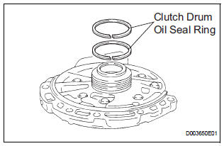
(a) Remove the 2 clutch drum oil seal rings.
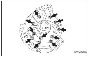
3. REMOVE STATOR SHAFT ASSEMBLY
(a) Using a "torx" socket (T30), remove the 11 bolts and stator shaft.
4. INSPECT CLEARANCE OF OIL PUMP ASSEMBLY
HINT: (See page AX-234)
5. REMOVE FRONT OIL PUMP DRIVE GEAR
(a) Remove the front oil pump drive gear.
6. REMOVE FRONT OIL PUMP DRIVEN GEAR
(a) Remove the front oil pump driven gear.
7. REMOVE FRONT OIL PUMP BODY O-RING
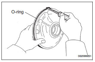
(a) Using a screwdriver, remove the O-ring.
HINT: Tape the screwdriver before use.
8. REMOVE FRONT OIL PUMP OIL SEAL
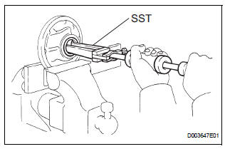
(a) Mount the oil pump in a soft jaw vise.
(b) Using SST, remove the oil seal from the oil pump body.
SST 09308-00010
 Oil pump
COMPONENTS
...
 Inspection
1. INSPECT OIL PUMP ASSEMBLY
(a) Turn the drive gear with the 2 screwdrivers and
make sure that it rotates smoothly.
NOTICE:
Be careful not to damage the oil seal lip.
2. INSPEC ...
Other materials:
System description
1. OUTLINE OF THEFT DETERRENT SYSTEM
When the theft deterrent system detects that the
vehicle is being tampered with, the system sets off
the alarm, causing the horns to sound and the lights
to light up or blink in order to alert people around the
vehicle to the theft.
The ...
Throttle / Pedal Position Sensor / Switch "A"
HINT:
These DTCs relate to the Throttle Position (TP) sensor.
DESCRIPTION
HINT:
This ETC (Electrical Throttle Control System) does not use a throttle cable.
The Throttle Position (TP) sensor is mounted on the throttle body, and detects
the opening angle of the
throttle valve. This sens ...
Removal
HINT:
Don't use the dropped or damaged yawrate sensor
Free from the foreign matters between yaerate sensor
bracket and body.
Make sure the sensor direction.
1. REMOVE FRONT SEAT ASSEMBLY RH
HINT:
See page SE-40.
2. REMOVE FRONT DOOR SCUFF PLATE RH
3. REMOVE COWL SIDE TRIM BOARD RH
...
