Toyota Sienna Service Manual: Disassembly
1. INSPECT PACK CLEARANCE OF FORWARD CLUTCH
HINT: (See page AX-242)
2. REMOVE FORWARD MULTIPLE DISC CLUTCH DISC

(a) Using a screwdriver, remove the snap ring.
(b) Remove the flange, 5 discs and 5 plates from the input shaft assembly.
3. REMOVE FORWARD CLUTCH RETURN SPRING SUB-ASSEMBLY
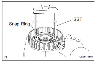
(a) Place SST on the spring retainer and compress the return spring with a press.
(b) Using a snap ring expander, remove the snap ring.
NOTICE:
- Stop the press when the spring seat is lowered 1 to 2 mm (0.039 to 0.078 in.) from the snap ring groove, preventing the spring seat from being deformed.
- Do not expand the snap ring excessively.
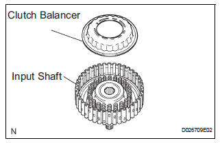
(c) Remove the clutch balancer from the input shaft.
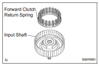
(d) Remove the forward clutch return spring from the input shaft.
4. REMOVE FORWARD CLUTCH RETURN SPRING SUB-ASSEMBLY
(a) Place the forward clutch drum onto the oil pump.
(b) Holding the forward clutch piston by hand, apply compressed air (392 kPa, 4.0 kgf/cm2, 57 psi) to the oil pump to remove the forward clutch piston.
HINT:
When the piston cannot be removed as it is slanted, blow air again with the protruding side pushed, or remove the piston using the needle nose pliers with vinyl tape on the tip.
5. REMOVE INPUT SHAFT OIL SEAL RING
(a) Remove the input shaft oil seal ring from the input shaft.
 Forward clutch
Components
...
 Inspection
1. INSPECT PACK CLEARANCE OF FORWARD CLUTCH
(a) Install the forward clutch on the oil pump.
NOTICE:
Be careful not to damage the oil seal ring of oil
pump.
b) Using a dial indicator, measure ...
Other materials:
Emergency flashers
The emergency flashers are used to warn other drivers when the
vehicle has to be stopped in the road due to a breakdown, etc.
Press the switch.
All the turn signal lights will flash.
To turn them off, press the switch
once again.
Emergency flashers
If the emergency flashers are used f ...
Sound Signal Circuit between Radio Receiver and Stereo Jack Adapter
DESCRIPTION
The stereo jack adapter sends an external device sound signal to the radio
receiver through this circuit.
The sound signal that has been sent is amplified by the stereo component
amplifier or radio receiver, and
then is sent to the speakers.
If there is an open or short in th ...
Throttle / Pedal Position Sensor / Switch "A"
Circuit Range / Performance Problem
DTC P0121 Throttle / Pedal Position Sensor / Switch "A"
Circuit Range / Performance Problem
HINT:
This DTC relates to the Throttle Position (TP) sensor.
DESCRIPTION
Refer to DTC P0120
DTC No.
DTC Detection Condition
Trouble Area
P0121
Differen ...
