Toyota Sienna Service Manual: Occupant Classification Sensor Power Supply Circuit Malfunction
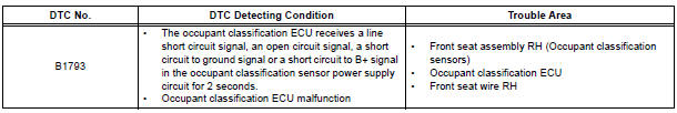
DTC B1793 Occupant Classification Sensor Power Supply Circuit Malfunction
DESCRIPTION
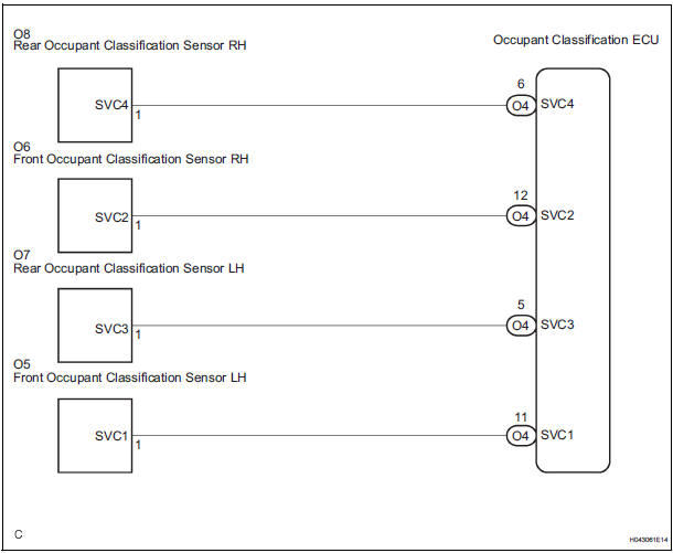
The occupant classification sensor power supply circuit consists of the occupant classification ECU and the occupant classification sensors.
DTC B1793 is recorded when a malfunction is detected in the occupant classification sensor power supply circuit
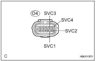
WIRING DIAGRAM
INSPECTION PROCEDURE
HINT:
- If troubleshooting (wire harness inspection) is difficult to perform, remove the front passenger seat installation bolts to see the under surface of the seat cushion.
- In the above case, hold the seat so that it does not fall down. Holding the seat for a long period of time may cause a problem, such as seat rail deformation. Hold the seat only as necessary.
1 CHECK DTC
- Turn the ignition switch to the ON position.
- Clear the DTCs stored in the memory.
HINT: First clear DTCs stored in the occupant classification ECU and then in the center airbag sensor assembly.
- Turn the ignition switch to the LOCK position.
- Turn the ignition switch to the ON position.
- Check the DTCs.
OK: DTC B1793 is not output.
HINT: Codes other than DTC B1793 may be output at this time, but they are not related to this check.
2 CHECK CONNECTION OF CONNECTORS
- Turn the ignition switch to the LOCK position.
- Disconnect the negative (-) terminal cable from the battery, and wait for at least 90 seconds.
- Check that the connectors are properly connected to the occupant classification ECU and the occupant classification sensors.
OK: The connectors are properly connected.
3 CHECK FRONT SEAT WIRE RH (SHORT TO B+)
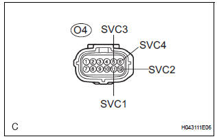
- Disconnect the connectors from the occupant classification ECU and the 4 occupant classification sensors.
- Connect the negative (-) terminal cable to the battery.
- Turn the ignition switch to the ON position.
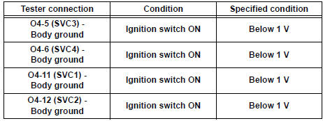
- Measure the voltage according to the value(s) in the table below.
Standard voltage
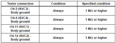
4 CHECK FRONT SEAT WIRE RH (SHORT TO GROUND)
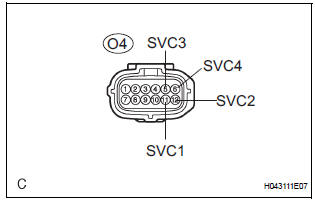
- Turn the ignition switch to the LOCK position.
- Disconnect the negative (-) terminal cable from the battery, and wait for at least 90 seconds.
- Measure the resistance according to the value(s) in the table below.
Standard resistance
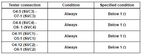
5 CHECK FRONT SEAT WIRE RH (OPEN)
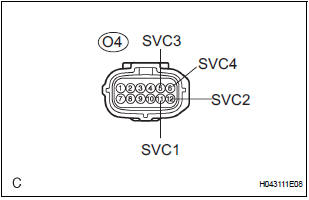
- Measure the resistance according to the value(s) in the table below.
Standard resistance
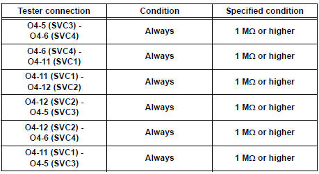
6 CHECK FRONT SEAT WIRE RH (SHORT)
- Measure the resistance according to the value(s) in the table below.
Standard resistance
7 CHECK DTC
- Connect the connectors to the occupant classification ECU and the 4 occupant classification sensors.
- Connect the negative (-) terminal cable to the battery.
- Turn the ignition switch to the ON position.
- Clear the DTCs stored in the memory
HINT: First clear DTCs stored in the occupant classification ECU and then in the center airbag sensor assembly. - Turn the ignition switch to the LOCK position.
- Turn the ignition switch to the ON position.
- Check the DTCs.
OK: DTC B1793 is not output.
HINT: Codes other than DTC B1793 may be output at this time, but they are not related to this check.
8 REPLACE OCCUPANT CLASSIFICATION ECU
- Turn the ignition switch to the LOCK position.
- Disconnect the negative (-) terminal cable from the battery, and wait for at least 90 seconds.
- Replace the occupant classification ECU.
HINT: Perform the inspection using parts from a normal vehicle if possible.
9 PERFORM ZERO POINT CALIBRATION
- Connect the negative (-) terminal cable to the battery.
- Connect the intelligent tester to the DLC3.
- Turn the ignition switch to the ON position.
- Using the intelligent tester, perform "Zero point calibration".
OK: "COMPLETED" is displayed.
10 PERFORM SENSITIVITY CHECK
- Using the intelligent tester, perform "Sensitivity check".
Standard value: 27 to 33 kg (59.52 to 72.75 lb)
11 CHECK DTC
- Turn the ignition switch to the ON position.
- Clear the DTCs stored in the memory.
HINT: First clear DTCs stored in the occupant classification ECU and then in the center airbag sensor assembly.
- Turn the ignition switch to the LOCK position.
- Turn the ignition switch to the ON position.
- Check the DTCs.
OK: DTC B1793 is not output.
HINT: Codes other than DTC B1793 may be output at this time, but they are related to this check.
12 REPLACE FRONT SEAT ASSEMBLY RH
- Turn the ignition switch to the LOCK position.
- Disconnect the negative (-) terminal cable from the battery, and wait for at least 90 seconds.
- Replace the front seat assembly RH ( for flat type, SE-48 for manual seat, SE-58 for power seat).
13 PERFORM ZERO POINT CALIBRATION
- Connect the negative (-) terminal cable to the battery.
- Connect the intelligent tester to the DLC3.
- Turn the ignition switch to the ON position.
- Using the intelligent tester, perform "Zero point calibration".
OK: "COMPLETED" is displayed.
14 PERFORM SENSITIVITY CHECK
- Using the intelligent tester, perform "Sensitivity check".
Standard value: 27 to 33 kg (59.52 to 72.75 lb)
END
 Center Airbag Sensor Assembly Communication
Circuit Malfunction
Center Airbag Sensor Assembly Communication
Circuit Malfunction
DTC B1790 Center Airbag Sensor Assembly Communication
Circuit Malfunction
DESCRIPTION
The center airbag sensor assembly communication circuit consists of the
occupant classification ECU and
the ...
 Open in Occupant Classification ECU Battery
Positive Line
Open in Occupant Classification ECU Battery
Positive Line
DTC B1794 Open in Occupant Classification ECU Battery
Positive Line
DESCRIPTION
This circuit consists of the occupant classification ECU and the power source
circuit (battery, fuse, wire
harness ...
Other materials:
Inspection
1. INSPECT LOWER BALL JOINT ASSEMBLY FRONT LH
(a) As shown in the illustration, flip the ball joint stud
back and forth 5 times, before installing the nut.
(b) Using a torque wrench, turn the nut continuously at
a rate of 3 - 5 seconds per 1 turn and take the
torque reading on the 5th tur ...
Installation
1. Install air fuel ratio sensor (for bank 2
sensor 1)
(a) Using SST, install the sensor to the exhaust
manifold LH.
SST 09224-00010
Torque: 40 N*m (408 kgf*cm, 30 ft.*lbf) for use
with SST
44 N*m (449 kgf*cm, 32 ft.*lbf) for use
without SST
HINT:
Use a torque wrench with a fulcrum ...
DVD Player Mechanical Error/ DVD Insertion and Ejection Error/ DVD Reading
Abnormal
DTC 44-10 DVD Player Mechanical Error
DTC 44-11 DVD Insertion and Ejection Error
DTC 44-12 DVD Reading Abnormal
DESCRIPTION
DTC No.
DTC Detecting Condition
Trouble Area
44-10
A mechanical error in the DVD player is detected while
the DVD is not being inser ...
