Toyota Sienna Service Manual: Mirror Motor Circuit
DESCRIPTION
A mirror control switch signal and memorized mirror positions are sent to the outer mirror control ECU.
The outer mirror control ECU drives the selected mirror UP, DOWN, LEFT and RIGHT in response to the inputs.
HINT: The power mirror control system is part of the large-scale multiplex communication system. This system features shared communication wiring that reduces the wiring complexity of the communication lines. The first step in any repair is to confirm the proper operation of the communication system. Proceed with troubleshooting after the communication has been verified (See Multiplex Communication System).
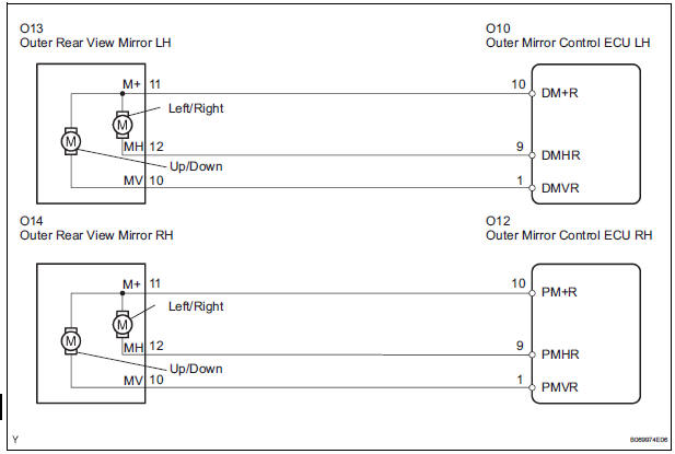
WIRING DIAGRAM
INSPECTION PROCEDURE
1 PERFORM ACTIVE TEST USING INTELLIGENT TESTER
- Connect the intelligent tester to the DLC3.
- Ignition switch on.
- Enter the following menus: DIAGNOSIS / ENHANCED OBD II / ACTIVE TEST.
- Select the ACTIVE TEST, use the intelligent tester to issue a control command, and then check that the outer rear view mirrors.
MIRROR-L/MIRROR-R

OK: Outer mirror operate normally.
2 INSPECT OUTER REAR VIEW MIRROR
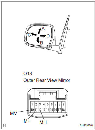
- Outer rear view mirror LH: Disconnect the O13 connector.
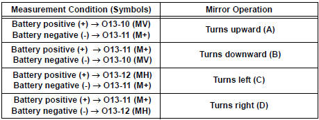
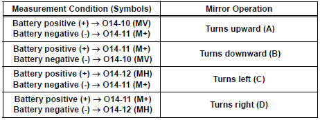
- Apply battery voltage and check operation of the mirror face.
Standard
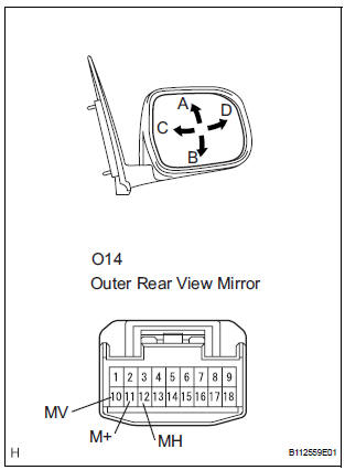
- Outer rear view mirror RH: Disconnect the O14 connector.
- Apply battery voltage and check operation of the mirror face.
Standard
3 CHECK HARNESS AND CONNECTOR (OUTER REAR VIEW MIRROR - OUTER MIRROR CONTROL ECU)
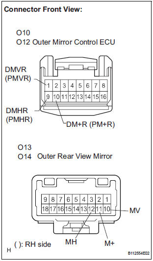
- Disconnect the O10 or O12 ECU connector.
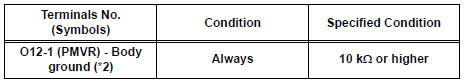
- Measure the resistance according to the value(s) in the table below.
Resistance
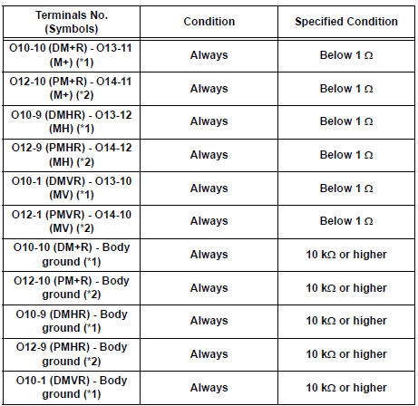
*1: LH side
*2: RH side
REPLACE OUTER MIRROR CONTROL ECU
 Mirror Switch Circuit
DESCRIPTION
A switch signal of the outer mirror switch is transmitted to the
selected outer mirror control ECU by way
of the body ECU. Then, the outer mirror control ECU activates the m ...
 Position Sensor Circuit
DESCRIPTION
When SET and 1 or 2 are pressed, the position sensor detects the mirror
position and sends the signal to
the outer mirror control ECU. Then when position 1 or 2 is pressed, the outer
...
Other materials:
Installation
1. INSTALL VVT SENSOR (for Bank 2 Exhaust Side)
Install the VVT sensor with the bolt.
Torque: 10 N*m (102 kgf*cm, 7 ft.*lbf)
Connect the VVT sensor connector.
2. INSTALL VVT SENSOR (for Bank 2 Intake Side)
Install the VVT sensor with the bolt.
Torque: 10 N* ...
Reassembly
1. INSTALL DIFFERENTIAL CASE SUB-ASSEMBLY NO.2
(a) Coat the front differential side gear thrust washer
No.1, front differential planetary ring gear, front
differential pinion No.2, front differential pinion thrust
washer No.2, front differential pinion shaft holder,
front differential pinio ...
Jam Protection Function Activates During Power Slide Door LH
Operation
DESCRIPTION
It may be caused by ill-fitting slide door, faulty touch sensor or
faulty pulse sensor.
The power slide door ECU activates the slide motor to open / close
the power slide door, thus
controlling the power slide door operation. For jam and foreign object
detect ...
