Toyota Sienna Service Manual: Disassembly
1. INSPECT PACK CLEARANCE OF REVERSE CLUTCH
HINT: (See page AX-249)
2. INSPECT PACK CLEARANCE OF DIRECT CLUTCH AND OVERDRIVE CLUTCH
HINT: (See page AX-249)
3. REMOVE DIRECT MULTIPLE DISC CLUTCH DISC
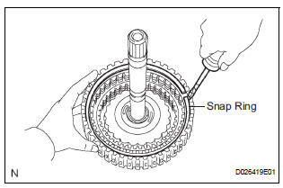
(a) Using a screwdriver, remove the snap ring from the intermediate shaft.
(b) Remove the flange, 3 discs, 3 plates and cushion plate from the intermediate shaft.
4. REMOVE OVERDRIVE DIRECT CLUTCH DISC
(a) Using a screwdriver, remove the snap ring from the intermediate shaft.
(b) Remove the flange, 4 discs and 4 plates from the intermediate shaft.
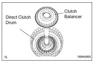
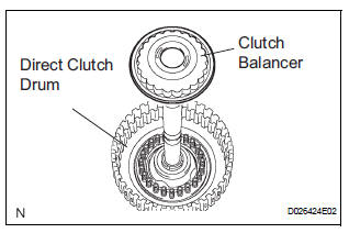
5. REMOVE OVERDRIVE CLUTCH RETURN SPRING SUB-ASSEMBLY
(a) Place SST on the clutch balancer and compress the spring with a press.
SST 09387-00020
(b) Using a snap ring expander, remove the snap ring from the direct clutch drum.
NOTICE:
- Stop the press when the spring seat is lowered to the place 1 to 2 mm (0.039 to 0.078 in.) from the snap ring groove.
- This prevents the spring seat from being deformed.
- Do not expand the snap ring excessively.
- This prevents the spring seat from being deformed.
- Do not expand the snap ring excessively.
(c) Remove the clutch balancer from the direct clutch drum.
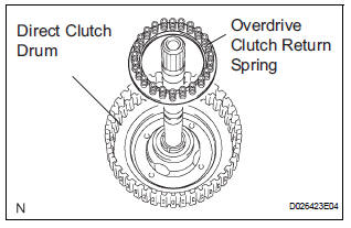
(d) Remove the overdrive clutch return spring from the direct clutch drum.
6. REMOVE OVERDRIVE DIRECT CLUTCH PISTON
(a) Install the intermediate shaft on the transaxle rear cover.
(b) Holding the direct clutch piston with your hand, apply compressed air (392 kPa, 4.0 kgf/cm2, 57 psi) to the transaxle rear cover to remove the direct clutch piston.
7. REMOVE OVERDRIVE DIRECT CLUTCH DRUM SUBASSEMBLY
(a) Holding the direct clutch drum by hand, apply compressed air (392 kPa, 4.0 kgf/cm2, 57 psi) to the transaxle rear cover to remove the direct clutch drum.
8. REMOVE OVERDRIVE DIRECT CLUTCH O-RING
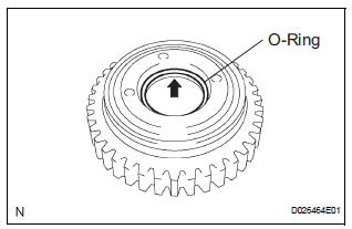
(a) Using a screwdriver, remove the O-ring from the direct clutch drum.
 Direct clutch
Components
...
 Inspection
1. Inspect pack clearance of reverse clutch
(A) install the intermediate shaft and needle roller
bearing onto the transaxle rear cover.
(B) using a dial indicator, measure the reverse clutch
...
Other materials:
Steering wheel audio
switches
Some audio features can be controlled using the switches on
the steering wheel.
Operation may differ depending on the type of audio system or
navigation system. For details, refer to the manual provided with
the audio system or navigation system.
Operating the audio system using the steering ...
Favorites list setting
Up to 15 contacts (maximum of 4 numbers per contact) can be registered
in the favorites list.
Registering the contacts in the favorites list
Select “Add Favorite”.
Select the desired contact to add to the favorites list.
Dimmed contacts are already stored as a favorite.
Check that a ...
Abnormal Temperature Inside ID1 Tire
DESCRIPTION
Each tire pressure warning valve and transmitter measures the internal
temperature of its tire as well as
tire pressure, and transmits the information to the tire pressure warning ECU
along with the transmitter ID.
If the measured temperature is out of the specified range, t ...
