Toyota Sienna Service Manual: Direct clutch
Toyota Sienna Service Manual / U151e automatic transaxle / Direct clutch
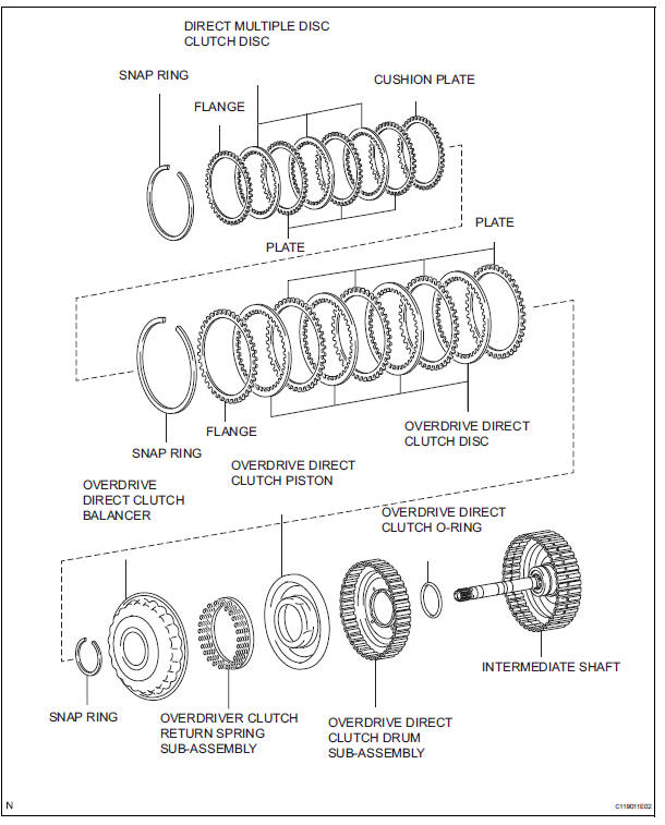
Components
 Reassembly
1. INSTALL INPUT SHAFT OIL SEAL RING
(a) Compress a new input shaft oil seal ring from both
sides to reduce dimension A.
Dimension A:
5 mm (0.197 in.)
(b) Coat the oil seal ring with ATF and ...
 Disassembly
1. INSPECT PACK CLEARANCE OF REVERSE CLUTCH
HINT:
(See page AX-249)
2. INSPECT PACK CLEARANCE OF DIRECT CLUTCH
AND OVERDRIVE CLUTCH
HINT:
(See page AX-249)
3. REMOVE DIRECT MULTIPLE DISC CLUTCH ...
Other materials:
Engine unit
COMPONENTS
...
Disassembly
1. REMOVE NO. 1 HEADLIGHT BULB (HALOGEN HEADLIGHT)
Turn in the direction indicated by the arrow and
remove the No. 1 headlight bulb.
2. REMOVE DISCHARGE HEADLIGHT BULB (DISCHARGE HEADLIGHT)
Turn in the direction indicated by the arrow and
disconnect the socket.
...
Warning lights and
indicators
The warning lights and indicators on the instrument cluster and
center panel inform the driver of the status of the vehicle’s various
systems.
For the purpose of explanation, the following illustration displays
all warning lights and indicators illuminated.
Vehicles with monochrome displ ...
© 2011-2026 Copyright www.tsienna.net
