Toyota Sienna Service Manual: Disassembly
1. SEPARATE REAR DRIVE SHAFT INBOARD JOINT BOOT CLAMP
(a) Using a screwdriver, remove the 2 rear drive shaft inboard joint boot clamps as shown in the illustration.
2. SEPARATE REAR DRIVE SHAFT INBOARD JOINT BOOT
(a) Separate the rear drive shaft inboard joint boot from the inboard joint assembly.
3. REMOVE REAR DRIVE SHAFT INBOARD JOINT ASSEMBLY
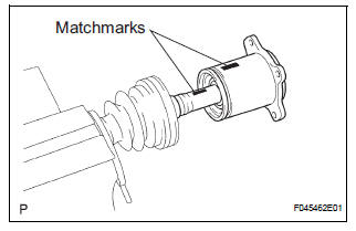
(a) Put matchmarks on the inboard joint assembly and outboard joint shaft.
NOTICE: Do not use a punch for the marks.
(b) Pull out the inboard joint assembly.
NOTICE: Be careful not to drop the balls.
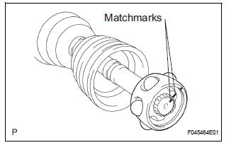
(c) Place matchmarks on the outboard joint shaft, inner race and cage.
NOTICE: Do not punch the marks.
(d) Remove the 6 bolts.
(e) Slide the cage toward outboard joint.
(f) Using a snap ring expander, remove the snap ring.
(g) Using a brass bar and hammer, remove the inner race.
(h) Remove the cage.
(i) Remove the inboard joint boot, inboard joint boot clamp and inboard joint boot No. 2 clamp.
4. REMOVE REAR DRIVE SHAFT OUTBOARD JOINT BOOT CLAMP
(a) Using pliers, remove the 2 rear drive shaft outboard joint boot clamps as shown in the illustration.
5. REMOVE REAR DRIVE SHAFT OUTBOARD JOINT BOOT
(a) Remove the outboard joint boot from the outboard joint shaft.
(b) Remove the old grease from the outboard joint.
NOTICE: Do not disassemble the outboard joint.
 Removal
1. REMOVE REAR WHEEL
2. REMOVE TAIL EXHAUST PIPE ASSEMBLY (See page
EX-8)
3. SEPARATE REAR SPEED SENSOR
(a) Remove the bolt and the speed sensor from the
axle carrier.
NOTICE:
Be careful not ...
 Inspection
1. INSPECT REAR DRIVE SHAFT ASSEMBLY LH
(a) Check that there is no remarkable play in the radial
direction of the outboard joint.
(b) Check that the inboard joint slides smoothly in the
thru ...
Other materials:
Checking and replacing
fuses
If any of the electrical components do not operate, a fuse may
have blown. If this happens, check and replace the fuses as necessary.
Turn the engine switch to the “LOCK” position (vehicles without a
smart key system) or off (vehicles with a smart key system).
Open the fuse box cover.
...
Precaution
1. INSPECTION PROCEDURE FOR VEHICLE INVOLVED
IN ACCIDENT
Perform the zero point calibration and sensitivity
check if any of the following conditions occur.
The occupant classification ECU is replaced.
Accessories (seatback tray and seat cover, etc.)
are installed.
...
Disposal
HINT:
When scrapping a vehicle equipped with the SRS or
disposing of the steering pad, be sure to deploy the airbag
first in accordance with the procedure described below. If any
abnormality occurs with airbag deployment, contact the
SERVICE DEPT. of TOYOTA MOTOR SALES, U.S.A., INC.
CAUTION:
...
