
Toyota Sienna Service Manual: Inspection
1. INSPECT REAR DRIVE SHAFT ASSEMBLY LH
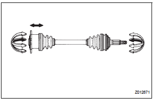
(a) Check that there is no remarkable play in the radial direction of the outboard joint.
(b) Check that the inboard joint slides smoothly in the thrust direction.
(c) Check that there is no remarkable play in the radial direction of the inboard joint.
(d) Check the boots for damage.
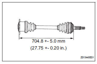
(e) Make sure that the 2 boots are not stretched or contracted when the drive shaft is at standard length.
Standard length: 704.8 +- 5.0 mm (27.748 +- 0.20 in.)
 Disassembly
1. SEPARATE REAR DRIVE SHAFT INBOARD JOINT BOOT CLAMP
(a) Using a screwdriver, remove the 2 rear drive shaft
inboard joint boot clamps as shown in the
illustration.
2. SEPARATE REAR DRIVE SHAF ...
 Reassembly
1. INSTALL REAR DRIVE SHAFT OUTBOARD JOINT BOOT
HINT:
Before install the boot, wrap the spline of the outboard
joint shaft with vinyl tape to prevent the boot from
bearing damaged.
(a) Instal ...
Other materials:
Rear Door ECU RH Communication Stop
DTC B1216 Rear Door ECU RH Communication Stop
DESCRIPTION
DTC B1216 is output when communication between the power slide door ECU RH
and the multiplex
network gateway ECU stops for more than 10 seconds.
DTC No.
DTC Detection Condition
Trouble Area
B1216
...
All Doors cannot be Locked / Unlocked at Once
DESCRIPTION
The body ECU receives a switch signal from the master switch, the door
control switch, the driver door
key cylinder and the passenger door key cylinder and then drives the door lock
motor.
WIRING DIAGRAM
INSPECTION PROCEDURE
1 INSPECT FUSE (ECU-B)
Remove ECU-B fuse f ...
Light Sensor Circuit Malfunction
DTC B1244 Light Sensor Circuit Malfunction
DESCRIPTION
This DTC is output when failure in the light sensor circuit is detected.
DTC No.
DTC Detection Condition
Trouble Area
B1244
Malfunction of automatic light control sensor
Open or short of a ...
