Toyota Sienna Service Manual: DTC check / clear
1. DTC CHECK (USING SST CHECK WIRE)
- Check the DTCs (Present trouble code).
- Turn the ignition switch ON, and wait for approximately 60 seconds.
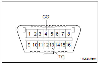
- Using SST, connect terminals TC and CG of the DLC3.
SST 09843-18040
NOTICE: Connect the terminals to the correct positions to avoid a malfunction.
- Check the DTCs (Past trouble code).
- Using SST, connect terminals TC and CG of the
DLC3.
SST 09843-18040
NOTICE: Connect the terminals to the correct positions to avoid a malfunction. - Turn the ignition switch ON, and wait for approximately 60 seconds.
- Read the DTCs.
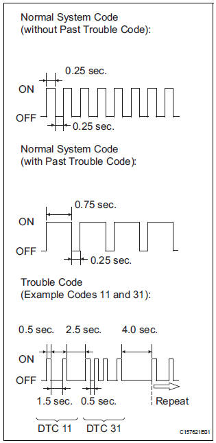
- Read the blinking patterns of the DTCs. As examples, the blinking patterns for the normal system code and trouble codes 11 and 31 are shown in the illustration.
- Normal system code indication (w/o past trouble code)
- he light blinks twice per second.
- Normal system code indication (w/ past trouble code)
- hen the past trouble code is stored in the center airbag sensor assembly, the light blinks only once per second.
- Trouble code indication
The first two blinkings indicate the first DTC.
The second blinking occurs after a 1.5- second pause.
If there are more than 1 code, there will be a 2.5- second pause between each code. After all codes are shown, there will be a 4.0-second pause, and they all will be repeated.
HINT:
- If 2 or more malfunctions are found, the indication begins with the smaller numbered code.
- If DTCs are indicated without connecting the terminals, proceed to the "Diagnosis Circuit"
2. DTC CLEAR (USING SST CHECK WIRE)
- Clear the DTCs.
- When the ignition switch is turned off, the DTCs
are cleared.
HINT: Depending on the DTC, the code may not be cleared by turning off the ignition switch. In this case, proceed to the next procedure.
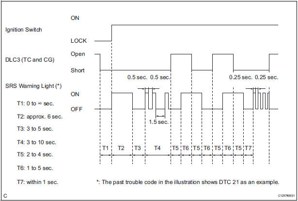
- Using SST, connect terminals TC and CG of the
DLC3, and then turn the ignition switch to the
ON position.
SST 09843-18040
- Disconnect terminal TC of the DLC3 within 3 to 10 seconds after the DTCs are output, and check if the SRS warning light comes on after 3 seconds.
- ) Within 2 to 4 seconds after the SRS warning light comes on, connect terminals TC and CG of the DLC3.
- ) The SRS warning light should go off within 2 to 4 seconds after connecting terminals TC and CG of the DLC3. Then, disconnect terminal TC within 2 to 4 seconds after the SRS warning light goes off.
- The SRS warning light comes on again within 2
to 4 seconds after disconnecting terminal TC.
Then, reconnect terminals TC and CG of the DLC3 within 2 to 4 seconds after the SRS warning light comes on.
- Check if the SRS warning light goes off within 2
to 4 seconds after connecting terminals TC and
CG of the DLC3. Also check if the normal
system code is output within 1 second after the
SRS warning light goes off.
If DTCs are not cleared, repeat this procedure until the codes are cleared.
3. DTC CHECK
- Check the DTCs.
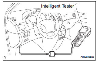
- Connect the intelligent tester to the DLC3.
- Turn the ignition switch to the ON position.
- Check the DTCs by following the prompts on the
tester screen.
HINT: Refer to the intelligent tester operator's manual for further details.
- Clear the DTCs.
- Connect the intelligent tester to the DLC3.
- Turn the ignition switch to the ON position.
- Clear the DTCs by following the prompts on the
tester screen.
HINT: Refer to the intelligent tester operator's manual for further details.
 Diagnosis system
1. CHECK DLC3
The ECU uses ISO 15765-4 for communication.
The terminal arrangement of the DLC3 complies
with SAE J1962 and matches the ISO 15765-4
format.
NOTICE:
*: Before ...
 Check mode procedure
1. CHECK MODE (SIGNAL CHECK): DTC CHECK
Connect the intelligent tester to the DLC3.
) Turn the ignition switch to the ON position.
) Select the "SIGNAL CHECK", and proceed
...
Other materials:
Terminals of ECU
1. FOLD SEAT CONTROL ECU LH
Disconnect the fold seat control ECU connectors.
Measure the voltage and resistance of the wire
harness side connectors.
If the result is not as specified, there may be a
malfunction on the wire harness side.
Reconnect the fold seat control E ...
Zero Point Calibration of Yaw Rate Sensor Undone
DESCRIPTION
The skid control ECU receives signals from the yaw rate sensor via CAN
communication system.
Yaw rate sensor has the built-in deceleration sensor.
If there is trouble in the bus lines between the yaw rate and deceleration
sensor and CAN communication
system, the DTC U0123 ...
Parking Brake Switch Circuit
DESCRIPTION
This circuit is from the parking brake switch to the radio and navigation
assembly.
WIRING DIAGRAM
INSPECTION PROCEDURE
1 CHECK BRAKE WARNING LIGHT
Check that the brake warning light comes on when the
parking brake is applied and goes off when it is released.
OK:
The ...
