Toyota Sienna Service Manual: Door Mirror Foot Light Circuit
DESCRIPTION
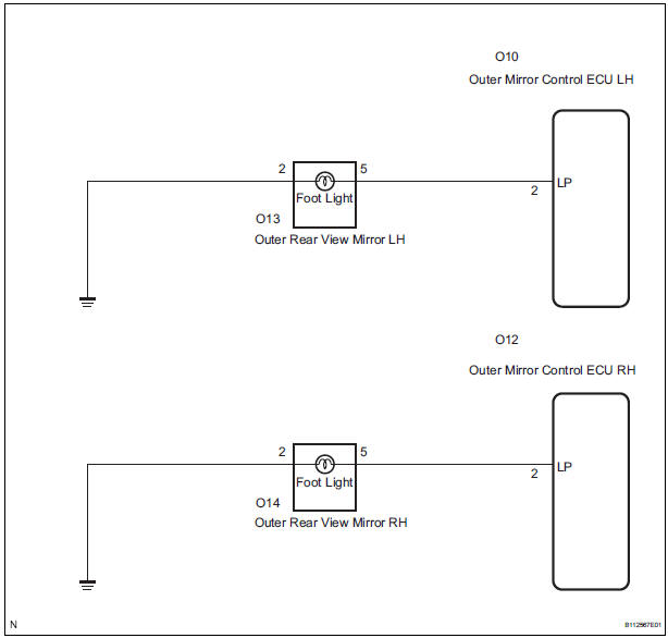
When the outer mirror control ECU receives the signal(s) from the body ECU through BEAN communication, it illuminates the foot light. The foot light is installed on the bottom of the outer rear view mirror and comes on or does off according to the following conditions.
The light comes on when:
- Doors are unlocked by wireless operation.
- The driver's door is manually unlocked with the shift lever is in the P position or the ignition off. (Both driver's and passenger's side come on.)
The light goes off when:
- Doors are locked by wireless operation.
- Doors are locked by the mechanical key.
- The setting time has elapsed after the light come on.
- The setting time has elapsed after the driver's or passenger's door is closed while the light is on.
- The ignition is off and the shift lever is in any position other than P.
- Doors are locked or unlocked by interlock operation or manual switch.
WIRING DIAGRAM
1 PERFORM ACTIVE TEST BY INTELLIGENT TESTER
- Connect the intelligent tester to the DLC3.
- Ignition switch on.
- Enter the following menus: DIAGNOSIS / ENHANCED OBD II / ACTIVE TEST.
- Select the ACTIVE TEST, use the intelligent tester to issue a control command, and then check that the outer rear view mirrors.
MIRROR-L/MIRROR-R

OK: Outer mirror foot light is light up.
2 CHECK HARNESS AND CONNECTOR (OUTER MIRROR CONTROL ECU - OUTER REAR VIEW MIRROR)
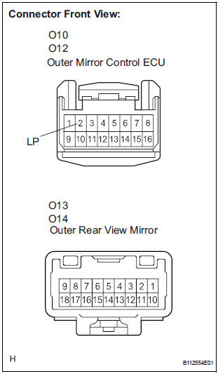
- Disconnect the O10 or O12 ECU connector.
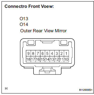
- Disconnect the O13 or O14 mirror connector.
- Measure the resistance according to the value(s) in the table below.
Resistance
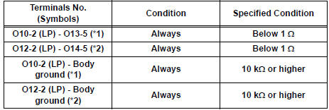
*1: LH side
*2: RH side
3 CHECK HARNESS AND CONNECTOR (OUTER REAR VIEW MIRROR - BODY GROUND)
- Measure the resistance according to the value(s) in the table below.
Resistance
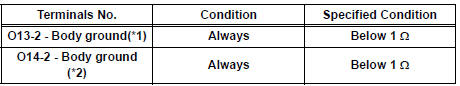
*1: LH side
*2: RH side
PROCEED TO NEXT CIRCUIT INSPECTION SHOWN IN PROBLEM SYMPTOMS TABLE
 On-vehicle inspection
1. CHECK POWER MIRROR SWITCH OPERATION
Remote control
The mirror adjust switch can control the adjustment
axis of the mirror surface.
Reverse-linked
This function tilts the mir ...
 Mirror Switch Circuit
DESCRIPTION
A switch signal of the outer mirror switch is transmitted to the
selected outer mirror control ECU by way
of the body ECU. Then, the outer mirror control ECU activates the m ...
Other materials:
Settings display
The settings of the following items can be changed, refer to
Language
Select to change the language on the display.
Units
Select to change the unit for measure of the fuel consumption and
outside temperature.
Eco Driving Indicator Light
Select to activate/deactivate the Eco Driving ...
Throttle Actuator Control Motor Current Range / Performance
DESCRIPTION
The ETCS (Electronic Throttle Control System) has a dedicated power supply
circuit. The voltage (+BM)
is monitored and when it is low (less than 4 V), the ECM determines that there
is a malfunction in the
ETCS and cuts off the current to the throttle actuator.
When the volt ...
Front seat frame with adjuster
Inspection
1. INSPECT FRONT SEAT ADJUSTER SUB-ASSEMBLY LH
Check operation of the seat frame (slide motor).
Check if the seat frame moves smoothly when
the battery is connected to the slide motor
connector terminals.
OK
If the result is not as specified, replace t ...
