Toyota Sienna Service Manual: Removal
1. REMOVE FRONT EXHAUST PIPE ASSEMBLY
HINT: (See page EX-8)
2. REMOVE PROPELLER WITH CENTER BEARING SHAFT ASSEMBLY
HINT: (See page PR-3)
3. REMOVE REAR DIFFERENTIAL FILLER PLUG
(a) Using a hexagon wrench (10 mm), remove the filler plug and gasket.
4. REMOVE REAR DIFFERENTIAL DRAIN PLUG
(a) Using a hexagon wrench (10 mm), remove the drain plug and gasket, and drain the oil.
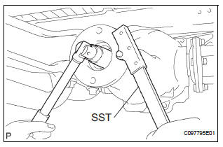
5. REMOVE REAR DRIVE PINION NUT
(a) Using a chisel and a hammer, unstake the staked part of the nut.
(b) Using SST to hold the flange, remove the nut.
SST 09330-00021
6. REMOVE REAR DRIVE PINION COMPANION FLANGE SUB-ASSEMBLY
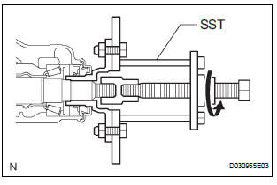
(a) Using SST, remove the companion flange.
SST 09950-30012 (09951-03010, 09953-03010, 09954-03010, 09955-03030, 09956-03020)
7. REMOVE REAR DIFFERENTIAL CARRIER OIL SEAL
(a) Using SST, remove the oil seal.
SST 09308-10010
8. REMOVE REAR DIFFERENTIAL DRIVE PINION OIL SLINGER
9. REMOVE REAR DRIVE PINION FRONT TAPERED ROLLER BEARING
(a) Using SST, remove the front tapered roller bearing.
SST 09556-22010
10. REMOVE REAR DIFFERENTIAL DRIVE PINION BEARING SPACER
 Rear differential carrier oil seal
COMPONENTS
...
 Installation
1. INSTALL REAR DIFFERENTIAL DRIVE PINION
BEARING SPACER
(a) Install a new bearing spacer.
2. INSTALL REAR DRIVE PINION FRONT TAPERED
ROLLER BEARING
(a) Install the tapered roller bearing.
3. IN ...
Other materials:
Reassembly
1. INSTALL REAR DOOR WIRE SUB-ASSEMBLY LH
Install the wire.
NOTICE:
When installing the wire, push the areas where
the clips are installed in order to prevent
damage and deformation.
Install the 2 screws.
2. INSTALL REAR DOOR LOCK ASSEMBLY LH
Apply MP grease to the slidi ...
Removal
HINT:
Remove the RH side by same procedures with LH side.
1. REMOVE FRONT WHEEL
2. REMOVE FRONT FENDER LINER LH
3. REMOVE FRONT SPEED SENSOR LH
(a) Disconnect the speed sensor connector.
(b) Remove the sensor harness and clamp from the
body.
(c) Remove the 2 clamp bolts holding the ...
Short to B+ in Front Pretensioner Squib LH Circuit
DTC B0138/72 Short to B+ in Front Pretensioner Squib LH Circuit
DESCRIPTION
The front pretensioner squib LH circuit consists of the center airbag sensor
assembly and the front seat
outer belt assembly LH.
This circuit instructs the SRS to deploy when deployment conditions are met.
DTC B01 ...
