Toyota Sienna 2010-2026 Owners Manual: Erasing the entire HomeLinkÂź memory (all three programs)
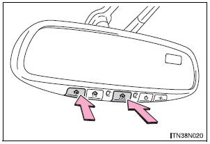
Press and hold down the 2 outside buttons for 10 seconds until the indicator light flashes.
If you sell your vehicle, be sure to erase the programs stored in the HomeLinkÂź memory.
Before programming
- Install a new battery in the transmitter.
- The battery side of the transmitter must be pointed away from the HomeLinkÂź button.
Certification for the garage door opener
- For vehicles sold in the U.S.A.
FCC ID: NZLWZLHL4
NOTE: This device complies with Part 15 of the FCC Rules.
Operation is subject to the following two conditions: (1) this device may not cause harmful interference, and (2) this device must accept any interference received, including interference that may cause undesired operation.
FCC WARNING: Changes or modifications not expressly approved by the party responsible for compliance could void the userâs authority to operate the equipment.
- For vehicles sold in Canada
NOTE: Operation is subject to the following two conditions: (1) this device may not cause interference, and (2) this device must accept any interference, including interference that may cause undesired operation of the device.
For additional programming assistance with your HomeLinkÂź Universal Transceiver
| WARNING When programming a garage door or other remote control device The garage door may operate, so ensure people and objects are out of danger to prevent potential harm. Conforming to federal safety standards Do not use the HomeLinkÂź Compatible Transceiver with any garage door opener or device that lacks safety stop and reverse features as required by federal safety standards. This includes any garage door that cannot detect an obstruction object. A door or device without these features increases the risk of death or serious injury. |
 Operating the HomeLink
Press the appropriate HomeLinkÂź button. The HomeLinkÂź indicator
light on the HomeLinkÂź transceiver should turn on.
The HomeLinkÂź continues to send a signal for up to 20 seconds as long as
the ...
 Compass
The compass on the inside rear view mirror indicates the direction
in which the vehicle is heading. ...
Other materials:
Customize parameters
HINT:
The following items can be customized.
NOTICE:
After confirming whether the items requested by the
customer are applicable or not for customization,
perform customizing operations.
Be sure to record the current settings before
customization.
When troubleshooti ...
Diagnostic trouble code chart
1. DTCS FOR OCCUPANT CLASSIFICATION SYSTEM
If a trouble code is displayed during the DTC check,
check the circuit listed for the code in the table below
(proceed to the page listed for that circuit).
HINT:
When DTC B1150/23 is detected as a result of
troubleshooting for the airbag system, pe ...
Check mode procedure
1. CHECK MODE (SIGNAL CHECK): DTC CHECK
Connect the intelligent tester to the DLC3.
) Turn the ignition switch to the ON position.
) Select the "SIGNAL CHECK", and proceed
checking using the intelligent tester.
NOTICE:
Select the "SIGNAL CHECK" from the &q ...
