Toyota Sienna Service Manual: Removal
HINT: On the RH side, use the same procedures as on the LH side.
1. REMOVE REAR NO. 1 SEAT ASSEMBLY LH
HINT:
- Captain seat type:
- Center seat type:
2. REMOVE REAR DOOR WEATHERSTRIP LH
3. REMOVE ROPE HOOK ASSEMBLY
4. REMOVE BACK DOOR SCUFF PLATE
5. REMOVE ROOF HEADLINING GARNISH REAR
6. REMOVE REAR DOOR SCUFF PLATE LH
7. REMOVE QUARTER TRIM PANEL ASSEMBLY LH
8. REMOVE RR WINDOW SIDE GARNISH ASSEMBLY NO.2 LH
9. REMOVE RR WINDOW SIDE GARNISH ASSEMBLY LH
10. REMOVE SIDE WINDOW ASSEMBLY REAR LH
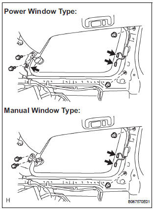
- Disconnect the connectors.
- Remove the 2 nuts and 2 bolts.
Torque: Bolt 5.5 N*m (56 kgf*cm, 49 in.*lbf)
- Remove the window.
11. REMOVE POWER VENT WINDOW MOTOR ASSEMBLY LH (POWER WINDOW TYPE)
- Using a screwdriver, remove the window motor.
12. REMOVE QUARTER WINDOW LOCK ASSEMBLY LH (MANUAL WINDOW TYPE)
- Remove the screw and window lock.
13. REMOVE SIDE REAR WINDOW WEATHERSTRIP LH
 Rear side window glass
COMPONENTS
...
 Installation
1. INSTALL SIDE REAR WINDOW WEATHERSTRIP LH
2. INSTALL QUARTER WINDOW LOCK ASSEMBLY LH
3. INSTALL POWER VENT WINDOW MOTOR
ASSEMBLY LH
4. INSTALL SIDE WINDOW ASSEMBLY REAR LH
5. INSTALL RR WINDOW ...
Other materials:
Reassembly
1. INSTALL FUEL PRESSURE REGULATOR ASSEMBLY
(a) Apply a light coat of gasoline or spindle oil to the 2
new O-rings, and install it to the fuel pressure
regulator.
(b) Apply a light coat of gasoline or spindle oil to the 2
O-rings again, and install the fuel pressure regulator
to the No. ...
Auto Up Operation does not Fully Close Power Window (Jam
Protection Function is Activated)
DESCRIPTION
If AUTO UP operation does not fully close the power window, the following
conditions may be the cause.
The reset of the power window motor has not been completed,
resulting in activation of the jam
protection function.
The memory of the power window switch misse ...
Installation
1. INSTALL CENTER AIRBAG SENSOR ASSEMBLY
Check that the ignition switch is off.
Check that the battery negative (-) terminal is
disconnected.
CAUTION:
After disconnecting the negative battery
terminal, wait for at least 90 seconds before
starting the operation.
Temporar ...
