Toyota Sienna Service Manual: Intake Air Temperature Sensor Gradient Too High
DTC P0111 Intake Air Temperature Sensor Gradient Too High
DESCRIPTION
The Intake Air Temperature (IAT) sensor, mounted on the Mass Air Flow (MAF) meter, monitors the IAT.
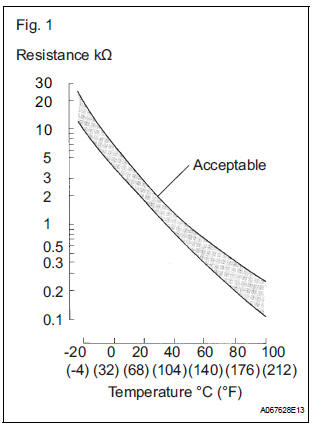
The IAT sensor has a built-in thermistor with a resistance that varies according to the temperature of the intake air. When the IAT becomes low, the resistance of the thermistor increases. When the temperature becomes high, the resistance drops. These variations in resistance are transmitted to the ECM as voltage changes (see Fig. 1).
The IAT sensor is powered by a 5 V supply from the THA terminal of the ECM, via resistor R.
Resistor R and the IAT sensor are connected in series. When the resistance value of the IAT sensor changes according to changes in the IAT, the voltage at terminal THA also varies. Based on this signal, the ECM increases the fuel injection volume when the engine is cold to improve driveability.
|
DTC No. |
DTC Detection Condition |
Trouble Area |
|
P0111 |
|
Mass air flow meter assembly |
MONITOR DESCRIPTION
The ECM performs OBD II monitoring based on the values from the intake air temperature sensor. If there is no change in the sensor value, the ECM will not be able to perform OBD II monitoring or will misdiagnose that there is a malfunction in the sensor. The ECM detects the stuck intake air temperature sensor value by performing monitoring after the ignition switch is turned off or the ignition is started (short soak or long soak).
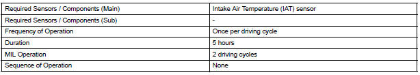
MONITOR STRATEGY

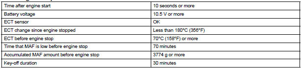
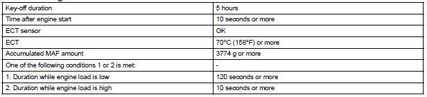
TYPICAL ENABLING CONDITIONS
All:

After engine stop:
After cold engine start:
TYPICAL MALFUNCTION THRESHOLDS
After engine stop:

After cold engine start:

WIRING DIAGRAM
Refer to DTC P0110.
INSPECTION PROCEDURE
1 CHECK ANY OTHER DTCS OUTPUT (IN ADDITION TO DTC P0111)
- Connect the intelligent tester to the DLC3.
- Turn the ignition switch to the ON position.
- Turn the tester on.
- Enter the following menus: DIAGNOSIS / ENHANCED OBD II / DTC INFO / CURRENT CODES.
- Read the DTCs.
Result

HINT: If any DTCs other than P0111 are output, troubleshoot those DTCs first.
GO TO DTC CHART
 Intake Air Temperature Circuit/ Intake Air Temperature Circuit Low Input/
Intake Air Temperature Circuit High Input
Intake Air Temperature Circuit/ Intake Air Temperature Circuit Low Input/
Intake Air Temperature Circuit High Input
DTC P0110 Intake Air Temperature Circuit
DTC P0112 Intake Air Temperature Circuit Low Input
DTC P0113 Intake Air Temperature Circuit High Input
DESCRIPTION
The Intake Air Temperature (IAT) sensor, ...
 Engine Coolant Temperature Circuit
DTC P0115 Engine Coolant Temperature Circuit
DTC P0117 Engine Coolant Temperature Circuit Low Input
DTC P0118 Engine Coolant Temperature Circuit High Input
DESCRIPTION
A thermistor is built into t ...
Other materials:
Disassembly
1. INSPECT UNDERDRIVE PLANETARY GEAR
PRELOAD
HINT:
(See page AX-260)
2. REMOVE FRONT PLANETARY GEAR NUT
(a) Using SST, loosen the staked part of the lock nut.
SST 09930-00010 (09931-00010, 09931-00020),
09387-00050
(b) Place the underdrive planetary gear in a soft jaw
vise.
NOTIC ...
Disassembly
1. INSPECT OIL PUMP ASSEMBLY
HINT:
(See page AX-234)
2. REMOVE CLUTCH DRUM OIL SEAL RING
(a) Remove the 2 clutch drum oil seal rings.
3. REMOVE STATOR SHAFT ASSEMBLY
(a) Using a "torx" socket (T30), remove the 11 bolts and
stator shaft.
4. INSPECT CLEARANCE OF OIL PUMP ASSEMBLY ...
Hazard warning switch
INSPECTION
1. HAZARD WARNING SIGNAL SWITCH ASSEMBLY
Check that there is resistance between the
terminals at each switch position as shown in the
chart.
Resistance
Inspect illumination operation.
Connect the positive (+) lead from the battery
to the termina ...
